Optocouplers Help Promote Safe, Efficient EV Charging Stations
This file type includes high-resolution graphics and schematics when applicable.
The worldwide electrification of transportation has grown rapidly through recent years. The global electric-vehicle (EV) stock was about 180,000 by the end of 2012. This number grew by 3.7 times, reaching more than 665,000 through the end of 2014 per IEA (International Energy Agency) Global EV Outlook reports. The report forecasts that by 2020, approximately 20 million EVs will be on the road.1
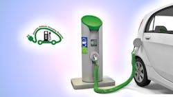
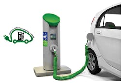
Rapid growth of the EV fleet is driving strong demand for a charging infrastructure to extend the vehicles’ travel range. An EV charging station, also called Electric Vehicle Supply Equipment (EVSE), supplies electric energy to the EVs while providing a network connection. EVs in this context refer to plug-in electric vehicles, including all-electric cars or battery electric vehicles (BEVs), electric buses, and plug-in hybrids (PHEVs). Figure 1 shows an EV at a charging station.
IHS Automotive forecasts the installation base for global EV charging stations to skyrocket from 1 million units in 2014 to 13.6 million by 2020. The market-research firm estimates that there will be 4.3 million units installed in the Americas; 4.1 million units in Europe, the Middle East, and Africa (EMEA); and 5.3 million in Asia (including Japan).2
Governments such as those in Germany, China, and the United States are steadily making more funds available to develop charging infrastructure. China, for example, plans to deploy 4.5 million EV charging stations by 2020.3 This effort will support the plan of cumulative production and sales of 5 million units of BEVs and PHEs by 2020, reports www.gov.cn, a website run by the central Chinese government.4,5 Compared to 31,000 charging stations built through the end of 2014,5 the target of 4.5 million units implies a whopping compound annual growth rate (CAGR) of 129%.
Charging-Station Standards
Along with the vast market opportunities provided by EV charging infrastructure, significant challenges need to be addressed. One involves the lack of harmonized standards for key elements in a charging system, such as the charge cord, protection mechanism, power rating, plug type and coupler configuration, and communication. Such issues becomes more critical for fast charging systems than the ac slow charging method, since fast charging systems are often installed at public or semi-public areas and meant to be shared. Obviously, incompatible systems make sharing difficult.
The International Electrotechnical Commission (IEC) has created a set of standards to cover EV charging. For example, IEC 61851-1:2010 EV applies to on-board and off-board equipment for charging EVs at standard ac supply voltages up to 1000 V and dc voltages up to 1500 V. IEC 61851-23:2014 provides the requirements for dc EV charging stations. For its part, IEC 62196-3:2014 specifies requirements for EV charging couplers.6,7
Globally, fast charging systems currently face competing standards—one being the CHAdeMO protocol adopted by the Japanese industry, and the other being SAE International’s J1772 Combined Charging System (CCS, also known as “Combo” standard) adopted by U.S. and German car manufacturers.1,8 They have different power-rating specifications, coupler designs, and communication protocols between EVSE and EV.
However, there are views stating “no standards war,” as their charging systems feature all-in-one designs for both CHAdeMO & SAE Combo standards. One example is the ABB’s Terra 53 Charge Station.9 Another relatively new competing standard is the Chinese GB/T 20234—a revised version was recently approved.10 Some designs, such as Tesla’s Superchargers, use proprietary charging technology.11
AC or DC Charging?
Putting aside the complication of standards, there are primarily two ways to transfer electricity from outside the vehicle to the battery inside: ac or dc. The grid transmits power in ac form, and energy stored in the on-board battery is in dc. Therefore, a charger is required to do the conversion job.
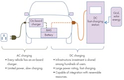
Depending on whether the charger is installed inside of the vehicle or not, chargers can be categorized into on-board charger (OBC) and off-board charging station. An OBC accepts an ac power source from the main supply available at home and at the consumer’s workplace, and converts it to dc to charge the battery. Typically, ac charging is slow due to the charger’s limited power rating—a constraint arising from the limitations of allowable weight, space, and cost.
The dc charging method is often used in off-board charging stations. It supplies regulated dc power directly to the batteries inside the vehicle. Because the dc charging equipment is installed at fixed locations with little constraint of size, its power rating can be as high as hundreds of kilowatts.
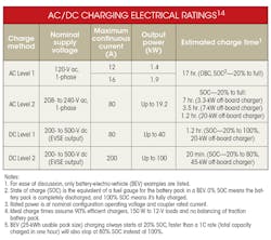
For example, SAE J1772 specifies up to 100 kW for DC Level 2.12 CHAdeMO considers 50 kW to be optimal output power, taking into consideration both the cost of securing the maximum power at the charger location and the time it takes to charge the battery.13 Tesla’s Superchargers consist of multiple Model S chargers working in parallel to deliver up to 120 kW of dc power directly to the battery. This charging rate equates to 170 miles of range in about 30 minutes.11 The dc fast-charging method shortens the charging time from hours to minutes.11,14 Figure 2 illustrates the ac and dc charging methods. The table below lists the ac and dc charging power ratings and estimated charge time for reference.
Charging speeds are different for ac and dc chargers, and both are essential in order to fit the EV drivers’ varied lifestyles. For example, an EV driver can use ac charge in the scenarios where ample time is available, such as parking at home or at a workplace. In contrast, dc fast charge can dramatically reduce charging time so that EV drivers can continue their journey quickly. Fast charging is a key factor in the successful roll-out of electric vehicles to reduce or eliminate range anxiety—especially for long-distance driving.
Charging-Station Topology and Safety Isolation
The need for safety isolation is present in all functions of an EV’s on-board electronic systems as well as in EV charging stations. On-board systems include the high-voltage battery management system, dc-dc converter, electric motor drive inverter, and on-board charger.16 For on-board systems, optocouplers must provide reinforced reliability and safety insulation capability, which suits applications such as gate driving, current/voltage sensing, and digital communication.17 Discussions in this article will focus on the isolation solution for off-board charger designs, which often find industrial-grade devices to be sufficient.
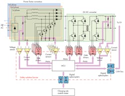
An EV charging station typically includes functional blocks, such as the ac-dc rectifier, power-factor-correction (PFC) stage, and dc-dc conversion to regulate the voltage to a level that’s suitable for charging the vehicle battery. Figure 3 shows a simplified block diagram of a dc-charging-station design. In high-frequency isolation topology, galvanic isolation is provided in the dc-dc converter stage by a high-frequency transformer. In addition, multiple isolation devices provide various signal isolation functions while maintaining a safety isolation barrier between the high-voltage power section and low-voltage controller section. Within all of these stages, power devices like MOSFETs and IGBTs are used to perform the switching functions.
Located in the center of the system is the microcontroller unit (MCU), which controls the PFC and dc-dc converter with pulse-width-modulation (PWM) signals. The charging control is based on voltage, current information, and other data, such as temperature, user inputs, etc., to carry out calculations and control instructions to fulfill the designed function. Digital communication ports are used to communicate between EVSE and the EV for charging control, and between EVSE and the charging-station control center and thereafter to the cloud for charging data reporting, remote monitoring, and diagnostics.
Optocouplers Deliver Galvanic Isolation, Efficient Charging
As seen in Figure 3, a safety isolation barrier is built up along the line formed by optical coupling points of the various optocouplers. This is important to ensure that the design safety aspects comply with regulatory standards. Besides galvanic isolation, the other key factor that often requires close attention in power converters, including the one in the EV charging station, is power-conversion efficiency. This article introduces how to use several optocouplers from the catalog17 to implement efficient charging-station designs for safety isolation.
Gate Drivers
In an EV charger, the MCU alters the PWM signals to switch the power MOSFETs or IGBTs on and off and adjust the duration of each status to regulate output voltage/current according to battery-charging mode. A PWM signal from the MCU normally needs amplification to increase output current in order to switch the power device at the desired frequency. It does so by driving the gate of a MOSFET or IGBT with a device simply called the gate driver.
Some gate-driver suppliers now provide a complete portfolio, from basic gate drivers to feature-rich integrated gate drivers, to meeting the design needs of efficient driving and protection.17 For instance, the ACPL-W346 gate driver features 2.5-A output current, rail-to-rail output voltage range, and a very short 55-ns propagation delay time. These electrical specifications are essential for designs tasked with delivering high power-conversion efficiency. Packaged in an SSO-6 small surface-mount device, this part has an isolation voltage rating of 5000 VRMS for one minute per UL1577 standard, and 1140 VPEAK per IEC/EN/DIN EN 60747-5-5 standard. These standard approvals will ensure the safety of the controller and user side.
In EV charging-station designs, besides choosing optimal power conversion topologies,18,19,20 choosing advanced power devices and appropriate gate drivers can help achieve efficiency goals. Silicon-carbide (SiC) MOSFETs are rapidly emerging into the commercial power-device market, delivering several benefits over conventional silicon-based power MOSFETs and IGBTs. One of the benefits is that it reduces switching losses because a high-voltage SiC MOSFET doesn’t have the tail current losses found with IGBTs. In addition, the SiC MOSFET’s high current density and small die size results in lower capacitance compared to silicon MOSFETs. Hence, higher switching-frequency operation is possible, which helps improve system efficiency.21
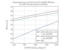
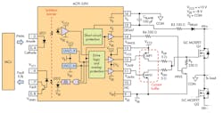
Results from one experiment22 show that the improvement is significant. Those designs used the ACPL-W346 and ACPL-339J with suitable buffer stages, respectively, to work with the Cree C2M SiC MOSFET in an 8-A, 100-kHz SEPIC dc-dc converter. At a 600-V blocking voltage level, the SiC MOSFET-based system achieves 4% better efficiency than the conventional IGBT-based design (Fig. 4). Figure 5 shows a simplified connection circuit using the ACPL-339J to drive the SiC MOSFET.
Voltage and Current Sensing
EV batteries employ three primary charging methods: constant voltage, constant current, and a combination of the two. Most EV charging systems use a constant voltage for the initial portion of the charging process, followed by a constant current for the final portion.24 To effectively implement these charging methods, voltage at various nodes and current through several branches need to be measured and fed back to the MCU for calculation, which will adjust PWM signals accordingly. For example, in Figure 3, voltages at the dc link and the charger output require continuous monitoring and accurate readings. Besides voltage information, currents in the PFC stage—through the input and output rails—are required to be measured.
Many studies7,19,25 on high-charging-efficiency systems include voltage and current information as basic parameters in control algorithm and power calculation, where accuracy of the information is critical. Charging voltage, current, and charging time constitute energy consumption during a charge, which will translate into a bill of charge. Therefore, a certain level of measurement accuracy is required.
One common method of measuring higher voltages uses a resistive potential divider to step down the voltage to a suitable level. A linear sensing chip then measures the voltage and sends it to the MCU. A current-sensing circuit often employs a precision shunt resistor to convert the current to a small voltage, which is sent to the MCU via some signal-conditioning devices.
However, it’s always a challenge when transmitting the signals accurately from high-voltage areas, such as the PFC and dc-dc converter stages, to the low-voltage controller side. This is due to high switching noise and ground loop noise across these two areas. These commonly encountered circuit problems can ruin data accuracy, damage the MCU, and threaten user safety. In these situations, isolation amplifiers like the ACPL-C87X and ACPL-C79X series are handy to carry out voltage- and current-sensing functions.26,27
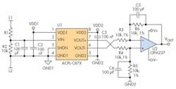
Using the ACPL-C87X isolated voltage sensor is straightforward. A detailed dc-voltage-sensing circuit with the ACPL-C87X is shown in Figure 6. Given that the ACPL-C87X’s nominal input voltage for VIN is 2 V, a user needs to choose resistor R1 according to R1 = (VL1-VIN)/VIN × R2. For example, if VL1 is 600 V and R2 is 10 kâ¦, then the value of R1 is 2990 kâ¦.
Several resistors can be combined to match the target value. For instance, 2-Mâ¦, 430-kâ¦, and 560-k⦠resistors in series equal exactly 2990 kâ¦. The downscaled input voltage is filtered by the anti-aliasing filter formed by R2 and C1 and then sensed by the ACPL-C87X. The isolated differential output voltage (VOUT+ – VOUT-) is converted to a single-ended signal (VOUT) via a post amplifier (U2). VOUT is linearly proportional to the line voltage on the high voltage side and can be safely connected to the system microcontroller. With the ACPL-C87X typical gain of 1, the overall transfer function is simply VOUT = VL1/(R1⁄R2+1).26
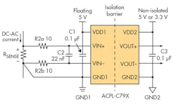
Using an isolation amplifier to sense current can be as simple as connecting a shunt resistor to the input and getting the differential output across the isolation barrier (Fig. 7). By choosing an appropriate shunt resistor, a wide range of current—from less than 1 A to more than 100 A—can be measured.
In operation, currents flow through the shunt resistor, and the resulting analog voltage drop is sensed by the ACPL-C79X. A differential output voltage is created on the other side of the optical isolation barrier. This differential output voltage is proportional to current amplitude and can be converted to a single-ended signal using an op amp, such as the post amplifier shown in Figure 6, or sent to the controller’s analog-to-digital converter (ADC) directly.27
Digital Communication
An advanced control scheme is necessary to implement a charging control protocol between the charging station and the EV. This is another area prone to divergent standards. For example, the SAE J1772 specifies the Control Pilot signal communication method using duty-cycle modulation for AC Level 1 and 2.12 For the digital communication required in dc charging, the SAE committee is working on updating the J2931, which proposes power-line-communication (PLC) schemes on the Control Pilot signal or mains.28 Tesla apparently participated in the SAE committee process and made the decision to use the same control signaling scheme as the SAE J1772.29
The most popular plug standard, CHAdeMO (based on EV sales with fast-charging type),2 chooses a controller area network (CAN) for fast charging. High communication reliability is required because the 500-V/100-A output of the dc fast charger could lead to a fatal accident if one error occurs, according to the Japanese association’s website. That association considers CAN to have a highly reliable record as a standard communication method for automotive electronic control systems. Its higher noise tolerance reportedly surpasses PLC as a communication method for an electronic control unit (ECU) to control the charging process ("FAQs – Technology"13).
The CHAdeMO standard provides a pair of CAN bus lines to connect the charger side and vehicle side at the coupler interface. Coupler pins 8 and 9 are assigned as CAN-H and CAN-L ("Technological details"13), respectively, to which a CAN transceiver can be connected.
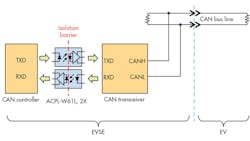
Adding optical isolation between the CAN transceiver and CAN controller significantly improves system safety, as optocouplers provide a safety barrier that prevents any damage from cascading to the system MCU. This arrangement also enables more reliable data communication in extremely noisy environments, such as high-voltage battery-charging systems. Figure 8 shows how to use optocouplers to implement isolated CAN bus digital communication for fast-charging-station designs. A similar circuit is applicable for the vehicle side, which requires automotive-grade parts.
In Figure 8, a pair of 10-MBd fast optocouplers (part ACPL-W61L) is used to transmit and receive data. The product, which requires just 1.6 mA of LED current, comes in an SSO-6 package less than half of the size of a traditional DIP-8 package. Per the UL1577 rating, the ACPL-W61L withstands high voltage of 5000 VRMS for one minute. Designed to transmit signals in the presence of strong transient noises, this part promises common-mode transient immunity of 35 kV/μs.30 In designs with different data speed other optocouplers can be used in place of the ACPL-W61L. These include the 5-MBd-rated ACPL-W21L,31 and the 25-MBb dual-channel bidirectional ACSL-7210.32
Conclusion
Ultimately, EVs help reduce dependence on petroleum within the world of transportation while tapping into often relatively inexpensive source of electricity. They also help reduce the emissions of greenhouse gases and other pollutants, which can be further improved as electricity generation portfolios add more renewable sources.
The EV charging infrastructure is a key factor in widespread EV adoption. In an EV charging station, especially dc fast charging, complex power-supply systems are employed to deliver huge amounts of energy to the battery in the vehicle within a short period of time. Safety isolation is imperative, since the low-voltage control system, high-voltage power system, and user-accessible user interface coexist in a single charging station.
Efficiency in energy conversion is another critical design consideration in EV chargers. Optocouplers, such as the gate drivers, voltage sensors, current sensors and digital communication optocouplers, deliver both safety isolation and respective electrical function in a single package, helping lead the way toward highly efficient systems.
Hong Lei Chen is a Product Manager in the Isolation Products Division at Avago Technologies. With over 15 years of experience in optocoupler product marketing, he has achieved various business-development objectives. He holds an M.Sc. in Microelectronics from Nanyang Technological University. Based in Singapore, he can be reached at [email protected].
References:
1. IEA, "Global EV Outlook - Understanding the Electric Vehicle Landscape to 2020," Edition 2013, and 2015 Update.
2. B. Scott, "Electric Vehicle Charging Infrastructure: 2015 Update," August, 2015; IHS Automotive Tech Report.
3. China Times, "Revised National Standard for Electric Vehicle Charging Station Releases in August," August 1, 2015.
4. The State Council of China, "State Council Issues Notice on the Development Plan (2012-2020) for Energy-Saving and New Energy Automotive Industry," June 28, 2012.
5. Xinhua News Agency, "China to Expedite Building Charging Infrastructure for 5 Million Electric Cars by 2020," October 4, 2015.
6. IEC, "IEC 61851-1:2010 Electric vehicle conductive charging system - Part 1: General requirements," November 25, 2010.
7. S.-H. Ahn, J.-W. Gong, H.-J. Ryoo, and S.-R. Jang, "Implementation of 60-kW Fast Charging System for Electric Vehicle," IECON 2013 - 39th Annual Conference of the IEEE, pp. 7256-7261, 2013.
8. M. C. Falvo, D. Sbordone, I. S. Bayram, and M. Devetsikiotis, "EV Charging Stations and Modes: International Standards," International Symposium on Power Electronics, pp. 1134-1139, 2014.
9. A. Bartosh, "EV Roadmap 7: DC Lessons," ABB EV Charging Infrastructure, 2014.
10. Xinhua News Agency, "China National Standard for Electric Vehicle Conductive Charge Coupler Approved," October 2, 2015.
11. Tesla Motors, "Superchargers."
12. SAE Internatioal, SAE J1772 Electric Vehicle and Plug in Hybrid Electric Vehicle Conductive Charge Coupler, 2012.
13. CHAdeMO Association.
14. SAE International, "SAE Charging Configurations and Ratings Terminology," ver. 100312, 2012.
15. M. Langezaal and C. Bouman, "Towards Winning Business Models for the EV-Charging Industry," ABB White Paper 4EVC200801-AREN, 2012.
16. M. Yilmaz and P. T. Krein, "Review of Battery Charger Topologies, Charging Power Levels, and Infrastructure for Plug-In Electric and Hybrid Vehicles," IEEE Transactions on Power Electronics, vol. 28, no. 5, pp. 2151-2169, 2013.
17. Avago Technologies, Optoisolation and Optical Sensor Products Selection Guide, AV00-0254EN, 2015.
18. L. Tan, B. Wu, S. Rivera and V. Yaramasu, "Comprehensive DC Power Balance Management in High-Power Three-Level DC–DC Converter for Electric Vehicle Fast Charging," Transactions on Power Electronics, IEEE, vol. 31, no. 1, pp. 89-100, 2015.
19. F. Musavi, W. Eberle, and W. G. Dunford, "Efficiency Evaluation of Single-Phase Solutions for AC-DC PFC Boost Converters for Plug-in-Hybrid Electric Vehicule Battery Chargers," Vehicle Power and Propulsion Conference (VPPC), IEEE, pp. 1-6, 2010.
20. Y. Zhang, J. Long, W. Gong, Y. Liu and B. Zhao, "Implementation of High Efficiency Batteries Charger for EV Based on PWM Rectifier," Vehicle Power and Propulsion Conference, IEEE, 2012.
21. S. Davis, "1200V SiC MOSFET Poised to Replace Si MOSFETs and IGBTs," Power Electronics Technology, February 2011.
22. R. Law and C. K. Tee, "SiC MOSFET Gate Drive Optocouplers," Avago Technologies, AV02-4498EN, 2014.
23. Avago Technologies, "ACPL-339J Gate Drive Optocoupler Interface," Datasheet AV02-3784EN, 2015.
24. S. Dhameja, Electric Vehicle Battery Systems, Boston: Newnes, 2002.
25. J. Channegowda, V. K. Pathipati and S. S. Williamson, "Comprehensive Review and Comparison of DC Fast Charging Converter Topologies: Improving Electric Vehicle Plug-to-Wheels Efficiency," IEEE 24th International Symposium on Industrial Electronics (ISIE), pp. 263-268, 2015.
26. Avago Technologies, "ACPL-C87B/C87A/C870 Precision Optically Isolated Voltage Sensor," Datasheet AV02-3563EN, 2013.
27. Avago Technologies, "ACPL-C79B/C79A/C790 Precision Miniature Isolation Amplifiers," Datasheet AV02-2460EN, 2014.
28. SAE International, "Digital Communications for Plug-in Electric Vehicles."
29. D. Tuttle, "Plug-In-Hybrid Electric Vehicle DC Fast Charging: The Future Just Got More Interesting."
30. Avago Technologies, "ACPL-W61L Ultra Low Power 10 MBd Digital CMOS Optocouplers," Datasheet AV02-2150EN, 2012.
31. Avago Technologies, "ACPL-W21L Low Power 5 MBd Digital CMOS Optocoupler," Datasheet AV02-3462EN, 2012.
32. Avago Technologies, "ACSL-7210 Dual-Channel (Bidirectional) 25 MBd CMOS Buffered Input Digital Optocoupler," Datasheet AV02-4235EN, 2013.
About the Author
Hong Lei Chen
Product Manager
Hong Lei Chen is a Product Manager of the Isolation Products Division at Avago Technologies. With over 15 years of experience in optocoupler product marketing, he has achieved various business-development objectives. He holds an M.Sc. in Microelectronics from Nanyang Technological University. Based in Singapore, he can be reached at [email protected].
