Power-Saving Tips When Rapid Prototyping ARM Cortex-M MCUs
This file type includes high-resolution graphics and schematics when applicable.
More and more, we’re seeing novel ideas, products, and applications arise from enthusiast developer communities rather than big corporations. Think of all the recent technology products from crowdfunding sites like Kickstarter, Indiegogo, and Tindie. With billions of devices projected to make up the Internet of Things (IoT), a wealth of opportunities awaits entrepreneurial developers. But before reaping the potential rewards, there are challenges to overcome.
Getting to market faster than the competition is imperative in today’s IoT era. The concept of being first to market with a viable product is widely accepted in the industry. To succeed with fast time to market, you need to shorten the development time. In the software/firmware engineering world, multiple rapid-prototyping frameworks have sprung up to accelerate this effort with various degrees of success.
Arduino might be the most commonly known framework, but a number of others are widely used in actual commercial products. For the ARM Cortex-M architecture alone, many more alternatives exist, including libopencm3, Espruino, and .NET Micro Framework (NETMF). These frameworks all have one thing in common: They’re not very effective in minimizing power consumption. And with increased focus on battery life for IoT connected devices, this becomes a major design challenge.
Where Does My Energy Go?
First, let’s take a step back and consider the relationship between power and energy consumption in semiconductors. Since microcontrollers (MCUs) basically comprise massive amounts of transistors set up as switches, the most important factor in the total power consumption is the active (or switching) power. Every switching transistor dissipates an amount of energy on each transition (equal to the load capacitance times supply voltage squared). More transitions per second (aka a higher core frequency) will thus lead to higher active power consumption, but also shorter execution time.
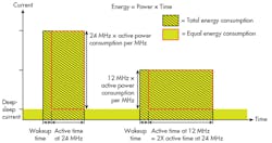
The total active energy consumed equals the instantaneous active power consumption multiplied by the time during which the circuit was consuming said power. Instinctively lowering the clock frequency thus will not produce gains in active energy consumption. Instead, you will end up with the exact same active energy expended as performing the same operation at a higher frequency, as shown in Figure 1 (area inside the red square).
Since other factors are at play, such as leakage current, switching time, and wakeup time, you’re generally better off reducing the active time and switching off the parts of the circuit you don’t need any more to get rid of the leakage in those parts. While this is counterintuitive, it’s generally better to execute your program as quickly as possible. This exposes another constraint—maximum execution speed.
Your MCU’s datasheet therefore mentions specs for maximum clock frequency, as well as a current consumption figure in the unit of current per megahertz. Peripherals often will have additional constraints on the clock frequency due to the transistors again: The smaller the transistor, the smaller its capacitance, and the less energy it will consume by switching. Its transition time will grow longer, though, leading to lower achievable speeds.
As a result, MCU vendors reduce power consumption by making design decisions on each part of the IC to find the most efficient mix of smaller, slower, but more energy-friendly transistors, versus bigger, faster and higher-power transistors. So if your application only needs a 1-MHz communications bus, it’s better to select an MCU with a maximum of 10 MHz versus one that scales to 100 MHz.
Sleeping—The Most Common Way to Cut Consumption
Since you can’t do anything about how the vendor sized the transistors or designed and laid out the circuit, we’ll move on to software techniques. For the purpose of this article, let’s select a generic MCU based on a Cortex-M0+ core, which in turn is based on the ARMv6-M microarchitecture.
By using this core, we already get some provisions to reduce power. From the “Cortex-M User Guide” (Chapter 2.5, Power Management), we see that two specific instructions are implemented: wait-for-event (WFE) and wait-for-interrupt (WFI). These instructions will halt the core execution until the occurrence of either an event or interrupt. To correlate this action with our power theory, it will switch off the clock to the processor core, meaning all of those transistors will stop switching, significantly reducing power consumption when you don’t need the core.
In addition, there’s a SLEEPDEEP bit in the core registers. According to the Cortex-M0+ User Guide, “regular” sleep mode stops the processor clock, while deep-sleep mode (when SLEEPDEEP is set) will stop the system clock, switch off the phase-locked loop (PLL), and switch off the flash memory. Deep sleep can have additional properties depending on the MCU vendor, since it’s defined by ARM as being partly implementation-specific, although vendors generally don’t diverge too much.
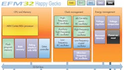
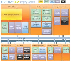
Depending on the vendor, the MCU can have even more power states, which you can use to your advantage. For example, Silicon Labs’ EFM32 Happy Gecko MCU has two more states: a stop mode, where only a few low-frequency or asynchronous peripherals are kept on; and a shutoff mode, when everything except external interrupts is switched off. Figure 2 indicates these modes respectively in dark blue (EM3 stop mode) or black (EM4 shutoff mode).
Since the modes are progressive, peripheral availability in a higher-power state is a superset of the lower-power state. Other vendors have similar setups; differences between them lie in which peripherals, parts of memory, and/or clock trees are kept on in which state. Read your MCU’s reference manual to find out.
Sleeping is a Tool, Not a Goal
You may think, “Okay, let’s get our program to go to sleep as quickly, as fast asleep, and as often as possible.” While you would be correct for the most part, another tradeoff should be considered. Waking up from a sleep mode requires time and energy, and these two variables change with how deep the MCU sleeps, as shown in the table. While switching between run mode and the first sleep mode might be quick and painless, switching in and out of deep sleep is definitely not due to the need to restart clocks and re-initialize peripherals.
For this reason, you should perform measurements on different versions of your code to determine if it’s more appropriate to use a higher-power sleep mode—or don’t go to sleep at all and reduce the clock frequency appropriately. This decision depends heavily on the actual code you are running, and the functionality you wish to obtain from your MCU. In the case of rapid development tools, it’s not something you can address in the lower layers, except for making certain assumptions based on the average use case.
Furthermore, putting the core into sleep mode through WFE/WFI isn’t guaranteed to turn off clocks to peripherals. Therefore, to save more energy, always turn off peripherals you no longer need before going to sleep.
Maximizing Sleep Time
Sleep mode is entered by calling WFE or WFI, and execution will resume when there’s an event or (enabled) interrupt pending, respectively. Thus, if you want to successfully implement a sleeping, power-efficient application, interrupts are needed to signal the core when to wake up to do processing. The best-known use case for interrupts is waiting for a user to press a button. Instead of constantly checking whether or not the button was pressed (and burning energy in the process), set up the MCU to generate an interrupt when the button is pressed. That way, the core can sleep until it receives the interrupt and then continue execution.
MCUs can do so much more than interpreting button presses. MCU peripherals have various degrees of being able to operate autonomously, and those peripherals use interrupts to signal to the core, “Hey, I’m done with my operation.” Autonomous operation is especially useful for long-running operations, such as transfers, ADC conversions, and waiting for a timer or RTC to expire.
The vast majority, if not all, of Cortex-M-based MCUs implement direct memory access (DMA). Therefore, you can move even more data between peripherals and RAM while the core is sleeping, resulting in longer sleeping times. Some MCU vendors take this technique of reducing processing core involvement even further. They allow you to implement custom logic (such as Cypress’ PSoC family) or have specific on-chip constructs (such as the Peripheral Reflex System of EFM32 MCUs) that enable peripherals to work together without waking up the core.
Since the processing core is the most power-hungry part of an MCU, doing as much as possible without its active involvement is the biggest impact you can have on reducing the MCU’s energy consumption.
Tradeoffs with Rapid Prototyping
Hold on! The initial reason we were going to use a rapid-prototyping framework was to reduce development time, not increase it by having to learn all of the special cases for various MCUs. We want to dive right into application development, and worry about the details later.
The typical constraints for rapid development are pretty much universal—the APIs must be easy to use; it should be easy to get started quickly without previous knowledge; and plenty of example code should be available to use as-is or spark new ideas. Preferably, the framework also doesn’t lock you into one particular vendor for reasons of portability and second-sourcing.
When applying these constraints, you may run into a few challenges in the framework’s abstraction layer. For example, as a provider of the lower hardware abstraction layers (HALs), you never know what the user is going to program and which peripherals will be used, and when. These uncertainties can complicate low-energy planning.
Opportunities actually present themselves at the intersection of low-power design goals and the ease of use of rapid-prototyping frameworks, even when they’re geared toward supporting multiple MCU vendors.
Change the Programming Model
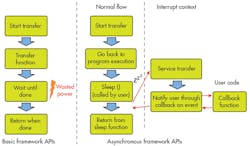
Consider the basic APIs for an MCU’s rapid-prototyping framework (not an RTOS). Odds are that the interface works something like the left side of Figure 3. When you want your system to do something, you call a function to do it, and that function returns when the action is complete. The framework is set up in this manner because the programming flow is simple and linear.
However, this approach comes with a major downside. Your program is stuck doing one task, so you can’t easily perform another task at the same time. The implementation could enable the function to go to sleep during the transfer, but then you run into other questions, such as “How deep do you sleep?” The answer depends on the other active peripherals, and how long they need to sleep until waking up again, as demonstrated previously. This can all be calculated and estimated dynamically, but that uses extra cycles, and thus energy.
To save power, we must therefore make changes in the way the underlying system works, and how the user interfaces with it. To that end, one can implement an “asynchronous programming model,” as illustrated on the right side of Figure 3. This means you call a function to start a long-running action, and that function immediately returns after setting up the system for the requested action. The action will then be executed in the background with the help of interrupts and possibly DMA transfers until completion, all of which is transparent to the user.
But what if the user wants to know that the transfer actually finished? In this case, the asynchronous model supports so-called callback functions. These functions can be written by the user and passed as an argument when calling the “start action” function. The callback function then gets called when the action is complete, or when something else happened to cause the action to be aborted, leveraging the power (savings) of autonomous operation.
Sleeping Revisited
Since all of this happens independently of the main program, the user can now be given the option of sleeping. By letting the user make the choice, we actually enable better ways to optimize power. The programmer knows the expected behavior of the application, so he/she can make a decision to sleep. Or the asynchronous action is too short, and going to sleep will actually consume more energy.
For the system to know how deep to sleep in such a case, it also must keep track of the peripherals in use and their power-mode constraints (e.g. through reference counting). Then, when the user calls sleep, you check those counters and go to the lowest possible sleep mode, turning off every idle clock to stop as many transistors as possible from switching.
Avoiding Race Conditions
Seasoned programmers will notice a problem here. Because the system is doing housekeeping (such as managing clocks and peripheral states) between deciding which sleep mode to enter and executing the actual WFI instruction, it’s possible that the action we were waiting for has already completed, and the callback function executed at that time. This is very inconvenient, since the decision on the sleep mode has already been made, but the conditions for that decision may have changed through the callback.
For example, if the callback was from a timer, but that callback started a serial transfer, it’s possible that the system will now continue entering a lower sleep mode than the serial transfer supports. This messes up the whole program behavior in the process—and possibly sleeping permanently.
The initial solution would be to switch off interrupts before making the decision, and switch them back on when returning from sleep. However, that would switch off the things that we’re actually waiting for by going to sleep, causing the sleep to be once again eternal. Turning on the interrupts right before the WFI/WFE instruction will cause all interrupts that happened between the time they were turned off and back on again to execute right before going to sleep, resulting in the same problem.
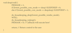
To prevent our MCU from turning into Sleeping Beauty, we need a prince to come and save us. It turns out that prince comes in the form of a bit in the Cortex-M core. That bit, called PRIMASK, disables all interrupts (except for the non-maskable ones, such as HardFault) from executing. But doesn’t that shut down our wakeup source?
When you examine the definition of the WFI instruction, you will see that it not only wakes up to service an interrupt, but also when an interrupt becomes pending that would have happened if PRIMASK wasn’t set. This means that if an interrupt occurred between making the decision and calling WFI, WFI will not put the core to sleep but rather return immediately. Also, turning off PRIMASK will result in the interrupt getting serviced, as indicated in Listing 1.
Real-World Example
To show what kind of impact this has on a real-world rapid-prototyping environment, we implemented these techniques inside of the ARM mbed framework. It provides an API that’s completely hardware-independent from a user’s perspective. The same application code can run on any Cortex-M MCU, regardless of the vendor, as long as the vendor implemented the mbed HAL for its MCU.
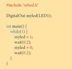
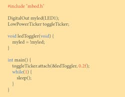
To demonstrate the effect of these changes, we measured the power consumption of two applications built with mbed—one simple blinking application (Listings 2 and 3), and one more advanced application (see this link for the full code) driving a graphical LCD while keeping track of time.
Starting with the blinking LED application, we can see in Figure 4 that the MCU uses 3.32 mA when burning cycles in a delay loop. The LED itself, which is on for half of the time, consumes 0.49 mA.
In the same figure, the low-power example uses 499.45 µA when the LED is on, and 1.38 µ A when off. Notice that spikes in the power consumption occur right before toggling the LED. These are the moments when the core wakes up and uses full power for a few cycles to actually toggle the LED. However, due to averaging in the power profiler, the spike doesn’t show all the way.
If we calculate the average current over a full cycle, we end up with an average current of 10 µA. That’s 0.3% of the MCU current during the regular example! If we then look at the total power consumption (including the LED) of the blinking LED application, there’s a drop from 3.57 mA to 0.26 mA average. That means your battery now suddenly lasts 13 times longer.
If we consider the example of driving an LCD with a clock on it, variations are a little less pronounced because we’re not disregarding the LCD’s consumption. Still, the results are impressive. Figure 5 shows the impact of different program functions on the application’s energy profile. Using the regular mbed APIs, the average current over one iteration is 3.06 mA. When we implement the same demo using the asynchronous programming model and sleep in between, we can reduce current consumption to a low 88 µA, leading to a factor 35 improvement in battery life.
Conclusion
While this article only scratches the surface regarding power-saving techniques, it’s clear that using a rapid development framework like ARM mbed OS should not be a battery-life killer. Using common, vendor-independent techniques can greatly reduce your application’s energy consumption, and that’s a great starting point for energy optimization.
Steven Cooreman, Software Engineering Manager, IoT MCU & Wireless, Silicon Labs, is a native of Belgium, Steven was involved in multiple exchange semesters while pursuing his electronics engineering education in Finland and the U.S. before joining Silicon Labs in Oslo, Norway. Steven currently works as Silicon Labs’ lead ARM mbed OS developer, focusing on the company’s 32-bit EFM32 Gecko portfolio.
References:
Using the new mbed power management API
Power consumption in CMOS, Carnegie Mellon 18-322 Fall 2003 course slides
About the Author
Steven Cooreman
Software Engineering Manager
Steven Cooreman, Software Engineering Manager, IoT MCU & Wireless, Silicon Labs, is a native of Belgium, Steven was involved in multiple exchange semesters while pursuing his electronics engineering education in Finland and the U.S. before joining Silicon Labs in Oslo, Norway. Steven currently works as Silicon Labs’ lead ARM mbed OS developer, focusing on the company’s 32-bit EFM32 Gecko portfolio.
