Simple NiCd Battery Charger Includes Charge Indication

This file type includes high resolution graphics and schematics.
Rechargeable nickel-cadmium (NiCd) batteries are widely used in consumer electronics because of their high energy density, long life, and low self-discharge rate. Standard NiCd cells can be charged at different rates: a fast charge with high current, or overnight with low current.
Regardless of the charge speed, a steady current should be provided to the battery during charging. Also, more energy must be supplied to the battery than its actual capacity to compensate for energy loss during charging.
However, two problems must be addressed when designing a charger for them: how to set the proper charging-current value, and how to stop the charging process when the battery is full, to avoid overcharging. This simple and inexpensive charger overcomes both problems.
The cheapest and safest way to charge a NiCd battery is to charge at 10% of its rated capacity per hour for 16 hours. The battery pack used contained two AA-size 1200-mAh NiCd cells, so the battery should be charged with 120-mA current.
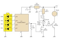
In the charging circuit of Figure 1, a constant charge current is generated by a current regulator comprising IC3 (an LM317 LDO) and resistor R3, where R3 is 1.25 V/120 mA, about 10 Ω. Switching MOSFET Q1 (IRF520) was chosen because of its very low open-state (conductive) impedance of 0.3 Ω.
The best charging practice is to use a timer to prevent overcharging to continue past 16 hours. This approach does not require an end-of-charge sensor, and it ensures a full charge. The timing function is performed by microcontroller IC1, which also reports the state of charge via the LEDs.
Related Articles
• Rechargeable-Battery Power Management Demands Multiple ICs
• Add Simple Temperature Monitoring To Battery-Management Systems
• New Battery Design Manages Wind And Solar Power’s Fluctuations
Any microcontroller could be used in this project. Here, the inexpensive eight-pin Motorola (Freescale) MC68HC908QT1 microcontroller was used.
Each charging step is indicated by lighting a corresponding LED. The number of steps is determined by the number of available outputs of the microcontroller, without adding any extra components. Since the microcontroller has five outputs, one of them is used for charge triggering, and so the four can be used for charge indication. To minimize the number of components, LEDs with built-in resistors are used (WP710A10YD5V, www.kingbrightusa.com).
To make the process more visual, these LEDs should be located in line with the outline of the battery drawn around them, so lighting the LEDs one by one will clearly indicate the progress of charging. It is reasonable to choose the time intervals to be equal, with the LEDs indicating 25%, 50%, 75%, and 100% of battery-charge time.
The program starts blinking the corresponding LED at the beginning of each time interval and up to the end of each interval. After that, it lights the LEDs steady on. When charging is over, all four LEDs are on, so the user knows the charge status at any time. (As an optional feature, a buzzer could be added to provide an audio signal when charging is over.)
The microcontroller program of Figure 2 is straightforward. The assembler code listing can be found here.

The LED blinking period is set at one second. The built-in oscillator of the microcontroller generates a frequency of 12.8 MHz and provides a one-cycle duration of 312.5 ns. By setting the timer prescaler to 64 and timer modulo register to 50,000 (C350H), the timer overflow (TOF) period is equal to one second (0.3125 μs × 64 × 50,000). The program toggles the LED at each TOF period.
The overnight “long” charge lasts 16 hours, with counter constant MAX_CNT calculated as 16 × 60 × 60 = 57,600 (E100H). Any maximum charge time can be set in the same way. Obviously, it’s not convenient to wait for 16 hours to test the program, and a period such as 20 minutes, for example, would be more practical.
For that shorter period, constant MAX_CNT should be set to 20 × 60 = 1200 (04B0H). The duration of each of four time intervals will then be automatically set by firmware once the maximum charge time is entered.
This approach is very flexible and can be applied to charge any NiCd battery by choosing resistor R3 accordingly. In addition, nearly any type of microcontroller can be used, because the program is simple and uses only standard instructions.
Abel Raynus is an engineer with Armatron International Inc., Malden, Mass. He can be reached at [email protected].
This file type includes high resolution graphics and schematics.
>> Electronic Design Resources
.. >> Library: Article Series
.. .. >> Series: Ideas for Design
.. .. .. >> Ideas for Design Volume 2
About the Author
Comment About the Article
To join the conversation, and become an exclusive member of Electronic Design, create an account today!

Leaders relevant to this article: