This file type includes high resolution graphics and schematics when applicable.
Next-generation EV charging faces challenges
The two most common automotive-industry charging standards are the Society of Automotive Engineers (SAE) standard J1772 in the USA, and IEC 61851 in Europe.
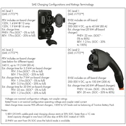
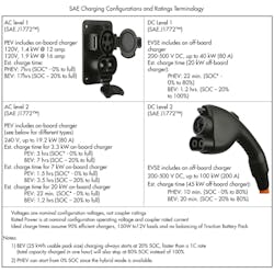
J1772 defines three charging levels (see figure). Level 1 is used when the charger is simply plugged into a 120-V wall socket, and it requires that the charger electronics be built into the car. Level 2 charging also assumes the electronics are in the car. But the charging source is single-phase ac at a nominal 240 V, with a maximum current capability of 32 A. Level 3 assumes that the vehicles charging electronics can handle either 120 or 240-V ac, via charging ports.
The drawback to either type of charging direct from a typical home ac power drop is that it’s slow. At 32 A, even 240-V is going to take many hours to replace the energy in an EV battery.
Dc charging, using a three-phase industrial-capacity ac power drop, can supply up to 600 V at 400 A. This could theoretically deliver 35 kWh in less than 10 minutes. The drawback to dc charging is that it isn’t cost-effective to put the electronics inside the car. With that requirement for external electronics, J1772 does accommodate dc charging. In fact, under J1772, Level 3 dc-capable vehicles could also be configured for dc charging with the addition of a serial data interface and some rearrangement of the internal wiring.
IEC61851 standard used in Europe and China was derived from J1772 and has similar requirements, adapted for the European and Asian ac line voltages. Most terminology differences are superficial. Where the SAE standard describes “methods” and “levels,” the IEC standard talks about “modes” — which are virtually the same.
For example, IEC61851 Mode 1 relates to household charging from single-phase 250-V (maximum) or three-phase 480-V power connections, with a maximum current of 16 A. There are further unique requirements for grounding.
IEC61851 Mode 2 uses the same voltages as Mode 1, but doubles the maximum allowable current to 32. Mode 2 also adds a requirement for a “control pilot function,” and an integral ground-fault interrupter. IEC61851 Mode 3 supports fast charging with currents up to 250 A. Above that, as with J1772, it allows an external dc supply that may supply up to 400 A.
This control pilot function is a handshake mechanism that keeps high voltages off the “hot” charging pins in the connector until the charging station connector is securely mated to the vehicle connector. This can be accomplished with a single signaling line in the connector. However, two other pins may be used to tell the electronics in the vehicle how much current the charging station is permitted to supply. The protocol for that is described in three other SAE body-communications standards: J1850, SAE J2178, and SAE J2293.
One of the most important things these standards do is to define safety requirements, although the methods for meeting them are left to connector manufacturers. “Safety,” in this case, means having a mechanical interlock that protects users from electric shock and provides further protection of the charging electronics and the traction battery.
What these standards do not do is describe the actual connectors. This has led to a variety of plug and socket configurations.
All the information above relates to North American and European standards. For Japanese cars, Tokyo Electric Power Company (TEPCO) has a patented fast-charging technology that uses dc voltage levels up to 500 V and currents up to 125 A. Under TEPCO’s CHAdeMO protocol, the vehicle exchanges battery parameters with the charging equipment. A CHAdeMO dc Fast Charge station delivers 62.5 kW (500 V dc at 125 A).
This file type includes high resolution graphics and schematics when applicable.
About the Author

Don Tuite
Don Tuite (retired) writes about Analog and Power issues for Electronic Design’s magazine and website. He has a BSEE and an M.S in Technical Communication, and has worked for companies in aerospace, broadcasting, test equipment, semiconductors, publishing, and media relations, focusing on developing insights that link technology, business, and communications. Don is also a ham radio operator (NR7X), private pilot, and motorcycle rider, and he’s not half bad on the 5-string banjo.


