Voltage-mode, Hysteretic, Or Hysteretic-Based: Which To Choose?
The traditional control topologies of voltage-mode and current-mode control are well known and studied by every power supply engineer. Less known are the hysteretic-based topologies and the advantages they bring. While pure hysteretic control may not be practical for certain applications such as medical or industrial automation, many newer power supply topologies are hysteretic-based with extra features to overcome the downsides of pure hysteretic control. These topologies find uses in everything from powering processor cores to automotive systems.
Related Articles
- Give Your Projects Under- And Overvoltage Protection With Hysteresis
- Voltage-Regulator Topology In A Nutshell
- Relate ADC Topologies And Performance To Applications
Almost all power supplies are designed to provide a regulated output voltage or current. Providing this output regulation requires a closed-loop system with a feedback of the output voltage or current to be regulated. While there are many different control topologies to close the feedback loop available, they may be generally grouped into two types: pulse-width modulation (PWM) or hysteretic. From these two fundamental topologies, a third evolves that is a blend of the first two: hysteretic-based. Each of these control topologies has advantages and disadvantages for different applications.
Voltage-mode Control
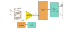
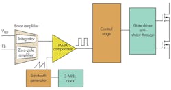
Pulse-width modulation (PWM) control is grouped into two basic types: voltage-mode and current-mode. For simplicity, this article discusses only voltage-mode control with input voltage feed-forward. See Reference 1 for a more detailed comparison of voltage-mode to current-mode control. Figure 1 shows the basic block diagram of voltage-mode control in a buck converter.2
When voltage-mode control is used to regulate the output voltage, it senses a scaled down version of the output voltage through a resistive voltage divider connected to its feedback (FB) input. The error amplifier then compares this FB signal to a high-accuracy, internal reference voltage, VREF, with a high gain. Loop compensation around the error amplifier keeps the system stable.
Voltage-mode control offers many advantages. By just regulating on the output voltage and other, well-controlled internal signals such as the clock and internal reference voltage, this topology is very noise immune. It also is fairly simple and straightforward. Simplicity is maintained with input voltage feed-forward, which keeps a constant loop gain over a varying input voltage. Furthermore, input voltage feed-forward allows a much better response to line transients. Finally, the clock enables control of the switching frequency, including the possibility to synchronize the circuit to an external clock source.
The main disadvantage of voltage-mode control is the required loop compensation and corresponding loop bandwidth limit. By its very nature, voltage-mode control introduces a double pole in the power stage, at the output filter’s corner frequency, which requires two properly located zeroes around the error amplifier. Because this double pole typically is low in frequency, the loop bandwidth is limited to lower levels. Generally, it is limited to no more than one-tenth of the switching frequency. This significantly and negatively affects the power supply’s transient response. The designer then must increase the output capacitance to achieve better transient results, which increases system cost.
With these tradeoffs in mind, voltage-mode control is still valuable, but especially in noise-sensitive applications. The noise immunity of voltage-mode control and its ability to synchronize to a system clock make it a good fit for the most noise-sensitive applications, such as medical and instrumentation devices.
Hysteretic Control
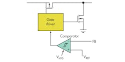
If there seems to be something missing, there’s not. Hysteretic control, in its pure and fundamental form, is extremely simple—the simplest of all control topologies (Fig. 2).3 A comparator with some small hysteresis between its terminals compares the output voltage, via its FB input, directly to the high-accuracy, internal reference voltage, VREF.
The advantage of such a direct control over the output voltage is the speed of the control loop. When the output voltage changes due to a transient, the time it takes for the control loop to begin to react is limited only by the propagation delays in the comparator and gate driver. There is no low-bandwidth error amplifier for an error signal to travel through. Thus, the hysteretic topology is the fastest control topology.
Additionally, its simplicity of operation makes it inherently stable without any loop compensation. This simplicity makes it a low-cost topology as well. There is no oscillator or error amplifier in the power supply to design, build, and test. Just a basic comparator is needed to control the switching action.
The main practical disadvantage of the hysteretic topology is its switching frequency variation. There is no clock or synchronization signal setting the switching frequency. Instead, the switching frequency is set by the hysteresis amount, as well as the external components and operating conditions.
Large frequency variations over input voltage and load are expected with a pure hysteretic converter. Moreover, without a high-gain error amplifier, the dc setpoint of the output voltage may not be as precise as achieved with voltage-mode control. Lastly, hysteretic control requires equivalent series resistance (ESR) in the output capacitor. Therefore, ceramic output capacitors with little ESR generally cannot be used with the pure hysteretic topology.
But in some low-power, very low-cost applications such as toys, a hysteretic converter might be acceptable due to the very low price point of such end equipment, as well as their low power, which produces low levels of electromagnetic interference (EMI) across the hysteretic power supply’s wide switching frequency range. Also, systems with very harsh transients require a hysteretic or hysteretic-based topology to keep acceptable regulation of the output voltage. If the input voltage, output voltage, and other operating conditions of these systems remain well controlled, the switching frequency is kept within an acceptable range. This makes hysteretic control a valid choice for applications operating from a fixed input voltage bus and creating a fixed output voltage.
Hysteretic-based Control
Numerous control topologies are fundamentally hysteretic but include other circuitry to overcome the frequency variation, and other pure hysteretic topology limits. These include, for example, the D-CAP, D-CAP2, COT, COT w/ERM, and DCS-Control topologies. This article analyzes and compares only DCS-Control4 and similar devices.
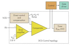
DCS-Control (direct control with seamless transition into power-save mode) fundamentally is a hysteretic topology, but one that blends some of the voltage-mode and current-mode features (Fig. 3). The hysteretic comparator compares the output of an error amplifier to a sawtooth waveform, as in voltage-mode control.
This sawtooth is not created from a clock. Instead, it is created through a special circuit connected directly to the output voltage at the VOS input pin. Essentially, the hysteretic comparator still has a direct connection to the output voltage through this VOS pin while a high-gain error amplifier is present to provide very good output voltage setpoint accuracy.
Besides combining the hysteretic comparator and error amplifier from the hysteretic and voltage-mode topologies, DCS-Control incorporates an on-time circuit to control the switching frequency. Finally, loop compensation is required and included for stability.
The main advantage of DCS-Control is keeping the very fast transient response of the hysteretic converter and the output voltage accuracy of the voltage-mode converter, while addressing other key disadvantages of both topologies: slow response time, limited control loop bandwidth, and frequency variation.
Because the VOS pin provides direct control over the output voltage, any change on the output voltage propagates directly through the control loop without being limited by the error amplifier’s bandwidth. This allows for a much faster transient response.
The main disadvantage of the current implementation of DCS-Control is that it cannot be synchronized to a clock. Being a hysteretic-based topology, there is no place for a clock input signal. Instead, it provides a controlled switching frequency that varies little over the operating conditions. In some cases, this variation is smaller than the tolerance on the clock frequency of a voltage-mode converter.
A hysteretic-based topology, such as DCS-Control, is best used in applications that see large transients and require the highest output voltage accuracy. These include powering processor cores in embedded or computing systems, as well as industrial automation and automotive infotainment systems.
Conclusion
The three main power supply control topologies of voltage-mode, hysteretic, and hysteretic-based each provide advantages and disadvantages for different applications. While most power supply engineers are comfortable with voltage-mode control, the hysteretic and hysteretic-based topologies provide best-in-class transient response and should be deeply investigated for applications such as powering processor cores that require such response. The plethora of devices available using each control topology means that there is likely an optimal power supply solution out there for almost any application.
References
1. Robert Mammano, Switching Power Supply Topology Voltage Mode vs. Current Mode, Design Note (SLUA119), Unitrode, 1994
2. 3-MHz 2A Step Down Converter in 2x2 SON Package, Datasheet (SLVS833B) Texas Instruments, November 2013
3. LM3475 Hysteretic PFET Buck Controller, Datasheet (SNVS239B), March 2013
4. Chris Glaser, High-efficiency, low-ripple DCS-Control™ offers seamless PWM/power-save transitions, Analog Applications Journal (SLYT513), Texas Instruments, 3Q13
Christopher James Glaser is an applications engineer for TI’s Low Power DC/DC group. In this role, he supports customers, designs evaluation modules (EVMs), writes application notes, trains field engineers and customers, and generates technical collateral to make TI parts easier to use. He received his BSEE from Texas A&M, College Station, Texas. He can be reached at [email protected].
About the Author
Chris Glaser
Applications Engineer
Christopher James Glaser is an applications engineer for TI’s Low Power DC/DC group. In this role, he supports customers, designs evaluation modules (EVMs), writes application notes, trains field engineers and customers, and generates technical collateral to make TI parts easier to use. He received his BSEE from Texas A&M, College Station, Texas. He can be reached at [email protected].


