110-V Op Amp Drives High Voltages and Currents into Capacitive Loads
What you’ll learn:
- The ADHV4710 op amp operates on dual supplies from ±12 to ±55 V, delivering output current of ±100 mA at the higher voltages.
- A ±1,300-V/μs output slew rate into capacitive loads up to 1 nF (1000 pF).
- The 80-pin, 12- × 12-mm TQFP EPAD-up package greatly reduces thermal-management constraints on the PCB layout.
Many operational amplifiers (op amps) are used at low signal levels—think of sensors or even RF preamplifiers. However, many situations crop up where the basic op-amp function is primarily as a driver with double- and triple-digit output voltage driving with currents of an amp or more. Adding to the challenge, many of their loads, such as piezoelectric transducers, are highly capacitive and can cause the amplifier to be unable to drive the load, become unstable, or worse.
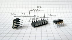
The need for higher output voltage and currents isn’t new, and many solutions have been devised to add a boost to the output of a lower-capacity device. These approaches generally involve adding external boosters using discrete bipolar transistors or MOSFETs to enhance the output (Fig. 1), and they look fairly simple in principle.
Engineering reality is never that simple, of course, and ensuring performance with respect to distortion through the zero crossing, drift, and other maladies usually requires additional components, detailed modeling, careful sizing of passive components such as resistors, and more.
Addressing the need for higher voltage or current output, vendors have developed advanced IC processes and adapted them to op amps targeting these applications, providing a more complete solution.
>>Check out this TechXchange for similar articles and videos
The Latest in High-Voltage Op Amps
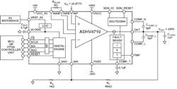
A new entry is Analog Devices’ ADHV4710, a high-voltage, high-power, high-speed operational amplifier optimized for driving up to ±1 A (continuous) at a ±1,300-V/μs slew rate into capacitive loads up to 1 nF (1,000 pF), as well as resistive loads (Fig. 2).
The ADHV4710 operates on dual supplies from ±12 to ±55 V, delivering output current of ±100 mA at the higher voltages. Asymmetrical dual supplies or a single supply of 110 V can also be used. It’s well-suited for applications such as driving automated test equipment (ATE), programmable power supplies, and piezo drive circuits. Quiescent current is just 12 mA.
This is more than just a high-power linear device. It combines a high-voltage amplifier with low-voltage analog circuitry and programmable SPI digital engine for setting fault-protection limits as well as threshold monitoring. The SPI interface can be used to digitally program current, voltage, and thermal shutdown limits.
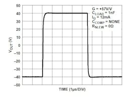
The amplifier is capable of high slew rate and bandwidth at high gain (Fig. 3), but it can alternatively be configured for low gain for high voltage input and output.
The external transconductance resistor supports stability under any gain and adjustable slew rate, while an external compensation capacitor enables the amplifier output to remain stable while driving unlimited capacitive loads.
What About Dissipation?
Whenever there’s high voltage combined with high current, thermal considerations are a factor. For the ADHV4710, the 80-pin, 12- × 12-mm TQFP EPAD-up package greatly reduces thermal-management constraints on the PCB layout.
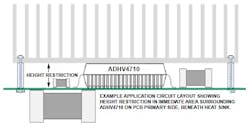
Conventional packages with their exposed pad (EPAD) on the underside require copper-filled vias or expensive solid copper coins pressed into the PCB for thermal conduction to a heatsink on the underside of the board. In contrast, the EPAD-up enables the heatsink to be mounted to the top of the ADHV4710, freeing up component space on the secondary side of the PCB and eliminating the need for through-board thermal relief.
Just four small mounting holes are required to secure the recommended heatsink to the PCB; these are located outside of the ADHV4710’s immediate area. Of course, the component heights on the primary side of the PCB in the area beneath the heatsink must be smaller than the minimum height of the ADHV4710 (Fig. 4).
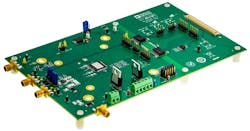
Support for this high-voltage op amp comes in two forms. First, there’s the 63-page ADHV4710 datasheet with numerous graphs, tables, and SPI setup/format details; second, there’s the EVAL-ADHV4710SDZ Evaluation Kit with its own 27-page User Guide (Fig. 5).
In addition to the loaded PCB, the kit includes an aluminum heatsink, tubeaxial fan, and basic mechanical components (screws and standoffs). The kit works in conjunction with the SDP-K1 controller board (purchased separately) and ACE software.
