Build A High-Frequency Portable Spectrum Analyzer Using Two Filter ICs
This file type includes high resolution graphics and schematics when applicable.
Designers sometimes need to analyze the spectrum of a modulated carrier. Although they can do this by down-converting and then digitizing and signal processing in the digital domain, the high-speed analog-to-digital converter (ADC) and the processor power required will reduce battery life. Instead, by down-converting in the analog domain and splitting the signals into discrete bands, the design can use a much slower, less power-hungry microcontroller.
Related Articles
- The Fundamentals Of Spectrum Analysis
- Understanding Signal Analyzer Architectures
- Use A Signal Analyzer To Measure Power Supply, Regulator, And Reference Noise
This can be achieved, for example, by using an IC such as Mixed Signal Integration’s Mixed Signal MiXer and Very High frequency Filter (MSMXVHF) to baseband, while the Mixed Signal Low powered Spectrum Analyzer (MSLSA) provides spectrum analyzer outputs at 1/6th-octave spacing.
The MSLSA sweeps with octave step increments using the 74HC4060 oscillator/divider and the 74HC151 one-of- eight selector. By selecting each output from the 74HC4060 with the 74HC151, one can quickly step through the baseband up to 100 kHz.
In the portable spectrum analyzer of Figure 1, the MSMXVHF includes a switching mixer that functions up to 600 MHz. The output of the mixer is limited to 1 MHz by a second-order, continuous-time low-pass filter. The MSMXVHF also features a selectable low-pass/band-pass switched-capacitor filter with operation up to 1 MHz (clock at 12.5 MHz). The output of the mixer is ac-coupled externally to the input of the filter, while the output of the filter is ac-coupled to the input of the MSLSA. The MSLSA has six outputs that can be monitored with a scope or the ADC of a microcontroller.

The 74HC4060 oscillator/clock divider has outputs at Q4 and continuing to Q12 (skipping Q11). The typical maximum-frequency crystal for the 74HC4060 at 3.3 V dc is 25 MHz. When the 74HC4060 is used with a 25-MHz crystal, the output at Q4 is 1.562 MHz. Figure 2 shows the output of the oscillator and the outputs Q4, Q5, and Q6 of the 74HC4060. These outputs are tied to the 74HC151, a 1-of-8 selector.

When S0, S1, and S2 are at a logic low, output D0 is selected. This output is tied to the MSLSA clock input. The MSLSA clock-to-corner ratio varies by each output. For Filter One output (1.12246), the clock to corner is 89.08:1. With a 1.562-MHz filter clock, the center frequency at Output One is 17.5 kHz.
Figure 3 shows the mixer input being swept around 25 MHz, with the mixer clock at 25 MHz, and the mixer output with the MSMXVHF filter set in low-pass configuration.

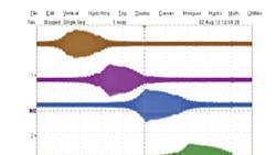
Figure 4 shows outputs 3, 4, 5, and 6 of the MSLSA with a swept input. Note that each output has an output frequency, when in range, of the MSLSA 1/6th-octave band-pass filter.

The MSMXVHF mixer/filter with the MSLSA low-power spectrum-analyzer integrated circuit with an oscillator, divider, and selector thus provides a solution for measuring distortion for received radio signals, while using less power than an all-digital solution.
John R. Ambrose is the vice president of applications and system engineering at Mixed Signal Integration Corp
About the Author
John Ambrose
Vice President of Engineering and System Engineering
John R. Amrbose is the vice president of applications and system engineering at Mixed Signal Integration Corp. He can be reached at [email protected].
Comment About the Article
To join the conversation, and become an exclusive member of Electronic Design, create an account today!

Leaders relevant to this article: