Dynamic loads create some of the most challenging application problems for power supplies. Rapidly changing currents or pulsed currents are extremely difficult to manage. Many devices under test (DUTs) impose rapidly changed currents or pulsed loads on their power supplies.
For battery-powered devices, like smart phones, designers will employ power management techniques to optimize runtime. Their power management algorithms will turn phone subsystems on and off to conserve power, producing a rapidly changing current.
A Global System for Mobile (GSM) transmit pulse will draw current with a slew rate of 0.15 A/µs during the approximately 600-µs wide transmit pulse. The fast edges of the transmit pulses will cause a regular power supply’s output voltage to droop during the pulse, resulting in the wrong voltage at the DUT during the transmit time and a lot of voltage instability as the pulses come and go.
For powerful microprocessors, the operating voltage is dropping from 3 V to less than 1 V. As the voltage drops, the current goes up. The current is rising, and the microprocessor’s high-speed operation means its current draw is also rapidly changing.
Once again, the power supply powering the DUT during the test will see high-speed currents that will cause its output voltage to droop. On a 1-V output, the droop can be several hundred millivolts, which renders the test invalid and could cause enough voltage rail instability that the whole system stops working.
Finding A Solution
Often, users will turn to their power supply vendors to solve this problem. To some degree, it’s possible for a vendor to create a power supply that tolerates rapid changes in current. But still, how rapidly the current changes, or the di/dt, is the critical factor.
For GSM speed pulses, it’s possible to create a power supply that can maintain its voltage output and regulate quickly enough to minimize the voltage droops. But at some point, the power supply can’t respond fast enough. Physics takes over and the inductance in the wires between the power supply and the DUT becomes the issue.
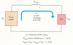
The formula V = L * di/dt dictates the voltage drop in the wires due to inductance. Common wire is approximately 0.1 µH per foot. Special low-inductance wire might be 5 to 10 nH per foot. Thus, if you have 100 A of current changing with a 1-µs rise time through a low inductance wire with 10 nH per foot, you will still see a 1-V of drop through the inductance of the wire (Fig. 1). And, in the opposite direction, when the current falls quickly, you will see voltage overshoot due to the wiring (also known as inductive kick).
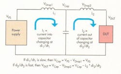
Decoupling capacitors often are used to minimize these rapidly changing currents and, thus, the voltage droop. But of course, these capacitors will only solve the problem between the power supply and the capacitor, where the capacitor will charge slowly and hold the voltage during the current transition so the power supply doesn’t see the high di/dt.
However, there will still be high di/dt between the capacitor and the DUT. These capacitors then must be very close to the DUT, so the inductance of the leads (or traces) between the decoupling capacitors and the DUT input will be small enough to minimize any voltage droop in the short current path between the capacitor and the DUT as rapidly changing current is pulled out of the capacitor (Fig. 2).
Still, sometimes the capacitors aren’t practical. The size of a capacitor large enough to reduce the di/dt may be too physically large to place close to the DUT, especially on miniaturized electronics. If you need to measure the current into the DUT, you can try to measure the current between the power supply and the capacitor, but you won’t see the true current flowing into the DUT. In fact, that’s why you put the capacitor there in the first place.
You’d then have to measure the current between the capacitor and the DUT. But common current sensors, like a current probe or a shunt, would require an extra lead length or trace to be inserted. And once again, the inductance of that extra lead or trace would become a problem by causing voltage droop.
So to manage high current pulses:
- Use low inductance wire.
- When using flexible wires between the power supply and the DUT, tightly bundle or preferably twist the positive output and negative output leads together to minimize loop area between the wires, which minimizes inductance.
- Avoid large connectors with wide separation between the pins. These separations increase the area between the leads, adding inductance.
- Put large capacitors as close as possible to the DUT, assuming space permits and the capacitor doesn’t interfere with the measurements or operation of the DUT.
- Use a high-quality power supply that can tolerate fast voltage transients. These specially designed power supplies are described as “dynamic power supplies,” “pulsed load power supplies,” or “high-speed power supplies.”
About the Author
Bob Zollo
Solution Architect for Battery Testing, Electronic Industrial Solutions Group
Bob Zollo is solution architect for battery testing for energy and automotive solutions in the Electronic Industrial Solutions Group of Keysight Technologies. Bob has been with Keysight since 1984 and holds a degree in electrical engineering from Stevens Institute of Technology, Hoboken, N.J. He can be contacted at [email protected].


