Today’s Oscilloscopes Tackle Evolving Communications Standards
This file type includes high resolution graphics and schematics when applicapable.
Oscilloscopes come in many shapes and sizes, with functionality ranging from simple signal capture to complex time-domain signal analysis. Recently, oscilloscope manufacturers have heeded user requests by enhancing the automated capabilities of their instruments so operators can achieve faster, more accurate measurements for increased productivity. In many cases, these automated measurements address high-speed serial communications parameters, with the aid of add-on personal-computer (PC) software.
Related Articles
- 12 Things To Consider When Choosing Your Next Oscilloscope
- Oscilloscopes Evolve From Center Instrument To The Only Instrument On Your Bench
- What's The Difference Between Real-Time And Sampling Oscilloscopes?
But as modern oscilloscopes incorporate more capabilities, such as built-in logic analyzers and waveform generators, operators are exploring parameter measurements for communications-standards-based equipment, including Wi-Fi wireless local-area networks (WLANs) and Long-Term Evolution (LTE) cellular communications components. In many cases, newer oscilloscopes offer real values in terms of performance and measurement capabilities.
Now Available
The range of oscilloscopes on the market is quite wide, in performance and price. Typically, an oscilloscope is specified according to the measurement requirements of a device under test (DUT). Quite simply, an oscilloscope displays voltage as a function of time, and it can do so for any type of signal it can process. By knowing the bounds of a DUT’s electromagnetic (EM) parameters, it is usually possible to find an oscilloscope to show the DUT’s EM performance. Most oscilloscope specifiers start with a handful of performance specifications for comparison, including bandwidth and sampling rate.
For high-frequency signals or signals with fast rise times, bandwidth is critical for analysis. An oscilloscope’s bandwidth indicates the frequency range across which it can make accurate measurements and across which signals are attenuated by no less than 3 dB in amplitude. Different test-equipment components offer different guidance on seeking bandwidth for an oscilloscope, such as the “three-times rule” or the “five times rule.”
For the latter, the bandwidth of the oscilloscope should be five times the highest-frequency component of a DUT’s signal of interest. The former rule refers to using the third-harmonic component of a DUT’s signal of interest to set the bandwidth requirement for an oscilloscope. Similarly, the faster an oscilloscope’s rise time, the more accurate will be its measurement and display of a DUT’s signal rise time.
Bandwidth is typically associated with price, with greater oscilloscope bandwidths translating into higher prices, so most instrument specifiers are careful about the instrument and amount of bandwidth that they select. While the upper-frequency limit of an oscilloscope does determine price, the lower-frequency limit is also worth noting since it can affect the instrument’s effectiveness for some measurements. Some measurements, such as electromagnetic-interference (EMI) testing, require a measurement range that extends well into the audio-frequency range or even with dc measurement capability.
In contrast, sampling rate, a parameter that defines the performance of digital oscilloscopes, has become more affordable with time so even lower-costing oscilloscopes are now available with impressive digital sampling circuitry with sampling rates of typically billions of bits per second (Gbits/s). Sampling rate is often tied to bandwidth (with some company guidelines calling for a sampling rate that is at least 2.5 times the bandwidth). However, some lower-bandwidth instruments also feature impressively high sampling rates and the corresponding ability to capture rapidly changing signal events and features. As sampling rate increases, the amount of memory required to store the data increases, with demand increased by the number of oscilloscope channels as well.
In sorting through oscilloscopes, it is important to recognize the many types currently in use and how they differ. Although a vanishing breed, analog oscilloscopes are still used, based on analog input and signal-processing electronics and usually a cathode-ray-tube (CRT) display screen to show measured signals. More common are the many types of digital oscilloscopes, which can be used to analyze analog and digital signals.
A digital storage oscilloscope (DSO) transforms analog input signals on a test channel to digital form by means of a high-speed analog-to-digital converter (ADC). By means of a microprocessor and digital signal processing (DSP), the waveform data is sent to the oscilloscope’s display screen, often an LCD, for viewing. Software within an oscilloscope enables automatic computation of key waveform parameters, such as rise time, fall time, amplitude, and pulse width. At one time, these instruments relied on the memory within a data converter or microprocessor to store captured waveform data. Ready availability of high-speed memory, though, makes it possible to store and process more data and greater amounts of waveform information per channel in a DSO.
Digital oscilloscopes are available based on different triggering methods. For example, a digital sampling oscilloscope can measure a waveform once per trigger, such as a point on the rise time of a pulse, when working in single-shot (or real time) mode. It also can operate in repetitive sampling modes, using multiple samples to capture different portions of a high-speed or high-frequency waveform and then assembling an image of the waveform on the oscilloscope’s display screen.
In this repetitive sampling mode, the performance and response of a digital sampling oscilloscope greatly depends upon the frequency response of the sampler used in the oscilloscope, but such an oscilloscope is effective at analyzing repetitive high-speed, high-frequency signals that are higher than the sampling rate of the oscilloscope. An excellent article, “What’s The Difference Between Real-Time And Sampling Oscilloscopes?” (http://electronicdesign.com/test-amp-measurement/what-s-difference-between-real-time-and-sampling-oscilloscopes) offers a contrast between using a digital sampling oscilloscope in single-shot and sampling modes.
A mixed-signal oscilloscope (MSO) combines a number of analog input channels with usually a greater number of digital input channels, providing synchronized measurements of the multiple inputs using a single time base and showing test results on a single display. While they may lack the large number of analysis channels of a dedicated logic analyzer, MSOs can provide great insight with a combination of oscilloscopes and logic analyzers.
A mixed-domain oscilloscope (MDO), as the name suggests, provides measurement capabilities in both the time and frequency domains. Some oscilloscope manufacturers have integrated basic spectrum-analysis functions within their digital oscilloscopes to allow displays of both voltage versus time and signal amplitude versus frequency—in essence, creating a miniature automated test system within the housing of the oscilloscope. Although the bandwidth of the spectrum analyzer is typically limited compared to that of the digital oscilloscope, the additional functionality can be quite useful when examining such signal characteristics as phase noise and stability.
Trends In Scopes
This incorporation of multiple measurement tools within an oscilloscope, in both benchtop and portable versions, represents a growing and positive trend for oscilloscope users. The multiple measurement channels can be triggered in synchronization, without the need to fine-tune complex external clock arrangements.
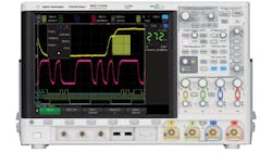
An example of this trend can be found in the InfiniiVision 4000X series of oscilloscopes from Agilent Technologies, with bandwidths as wide as 1.5 GHz and sampling rates to 5 Gsamples/s for the analog channels (somewhat less for digital inputs). The InfiniiVision MSO-X 4154A packs a multiple-channel oscilloscope, a logic analyzer, a three-digital digital voltmeter (DVM), a dual-channel function-generator/arbitrary waveform generator (AWG), and a serial protocol analyzer into the enclosure once used for just an oscilloscope (Fig. 1).

All five functions, including the oscilloscope and its bandwidth, can be upgraded for changing measurement requirements. To assist in creating waveforms with the 20-MHz AWG, the firm offers a free copy of the BenchLink Waveform Builder Basic software on its website (at www.agilent.com/find/33503). With its two channels, the AWG can produce modulated and differential signals.
As with other members of the InfiniiVision 4000X series, the MSO-X 4154A shows captured signals on a 12.1-in. capacitive touchscreen, updating the display at rates to 1 million waveforms/s. The display screen even helps with triggering on portions of a waveform—by drawing borders around a portion of interest on a displayed signal, that part of the signal will be triggered for future measurements.
The screen provides 8-b standard vertical resolution and includes a high-resolution display mode with 12-b effective vertical resolution. For those not enamored of the touchscreen, its functionality can be shut off and the MSO-X 4154A can operate like a traditional display screen with the push of a button.
Agilent, with a portfolio of oscilloscopes ranging from 20 MHz to 90 GHz, is offering a discount for customers seeking additional bandwidth from its 1000A, 1000B, 2000X, 3000X, or 4000X series oscilloscopes, as part of the “Supercharge Your Oscilloscope Bandwidth” promotion (through March 31). Oscilloscope customers can choose a model with a higher bandwidth than they would normally afford, paying the price of the selected model to the next lower bandwidth with the same family and with the same number of channels.
Tektronix made noise several years ago by adding spectrum-analysis measurement capabilities to its MDO4000B series of MDOs, capabilities that it recently enhanced further late last year (Fig. 2). The multiple-function capabilities of the MDO4000B instruments transform them into hybrid measurement systems capable of performing time- and frequency-domain measurements.
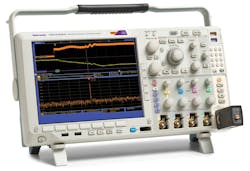
When equipped with the Live Link option and the company’s SignalVu-PC vector-signal-analysis (VSA) software, the hardware and software can provide the analysis functions of an RF/microwave VSA. Options for the software enable analysis of IEEE 802.11 a/b/g/j/n/p/ac Wi-Fi signal quality, pulse quality for radar systems, general-purpose digital modulation, and amplitude modulation (AM), frequency modulation (FM), and pulse modulation (PM) quality.
Tektronix reports that the oscilloscope series has gained in popularity as engineers face a growing number of communications interfaces with integrated RF/microwave circuitry, including Wi-Fi, ZigBee, and radio-frequency identification (RFID). According to Fanny Mlinarsky, president and CTO of wireless test services provider octoScope, “The MDO4000B with SignalVu-PC delivers the right capabilities at the right price point to enable embedded and WLAN module designers to rapidly debug systems without a steep learning curve.”
Jim McGillivary, general manager for Tektronix’s Source Analyzer Product Line, sees the new version of the oscilloscope as a great boost in the growing use of WLAN technology: “With the emergence of the ‘Internet of Things,’ more and more products are incorporating WLAN and they all need to pass compliance tests. There is a huge market need for better WLAN test solutions across all phases of the product lifecycle. We are meeting this need with better usability at about half the cost of alternatives.”
The enhancements to the oscilloscopes’ spectrum-analysis capabilities include spurious-free dynamic range (SFDR) of –60 dBc guaranteed and typically –65 dBc (an improvement from levels of –55 and –60 dBc in earlier models) and an improvement of as much as 20 dB in spectrum-analyzer phase-noise performance for greater confidence in evaluating spurious and low-level signals. In addition, the integral spectrum analyzer’s lower-frequency limit has dropped to 9 kHz (formerly 50 kHz) for improved EMI diagnostics while the maximum RF/microwave acquisition time has essentially doubled, increasing from 79 ms to a current capacity of 158 ms.
These improved spectrum-analysis capabilities, when used with the SignalVu-PC software, support advanced modulation analysis of wireless standards such as the various configurations of IEEE 802.11. In addition to characterizing WLANs, the software/oscilloscope combination is a powerful tool for testing wideband radar systems, frequency-agile communications systems, and satellite-communications (satcom) equipment.
An important feature in newer oscilloscopes, such as the MDO4000B line, is signal integrity (SI) testing, since SI more and more is being used to characterize the quality of modern communications systems. SI can be degraded by analog and digital causes, including crosstalk from signal traces in close proximity, ground bounce, signal reflections, jitter, and circuit layout problems.
Oscilloscopes with sufficient bandwidth and eye diagram capability can help spot SI problems, since such diagrams can reveal serial data and logic transitions in a single view. The number of high-performance oscilloscopes that include eye diagrams and, ideally, simplify matters with one-button eye-diagram measurements is growing.
In terms of future developments, Tektronix announced last year that it would base its next line of high-performance real-time oscilloscopes on silicon-germanium (SiGe) semiconductors from IBM. Using that firm’s 9HP SiGe process, which yields devices at transition frequencies to 350 GHz, Tektronix expects to achieve instruments with real-time bandwidths to 70 GHz in support of high-speed data communications.
“The advanced 9HP SiGe BiCMOS technology provides the faster switching speeds, high integration levels, and low noise our next generation of performance instrumentation requires to meet customer requirements,” said Kevin Ilcisin, chief technology officer (CTO) of Tektronix. The next-generation oscilloscopes will also leverage asynchronous-time-interleaving technology for improved signal-to-noise performance.
As part of the company’s efforts to enhance instrument performance, the R&S RTO series oscilloscopes from Rohde & Schwarz include a unit with measurement bandwidth to 4 GHz, the R&S RTO1044. With sampling rates of 10 Gsamples/s for four-channel operation and 20 Gsamples/s for two-channel use, the oscilloscope provides 8-b vertical resolution and as many as 600,000 waveforms/s with 100-ps rise/fall time resolution. It shows results on a 10.4-in. liquid-crystal thin-film transistor (TFT) color display with touchscreen functionality.
As with the other digital oscilloscopes in the RTO series, the R&S RTO1044 offers full math functions and full fast Fourier transform (FFT) spectrum analysis per user-defined parameters, such as center frequency and Gaussian bandwidth. As with many newer high-resolution digital oscilloscopes, it can work with PC-based software to provide automated measurements per high-speed serial communications standards and even to some of the requirements of Wi-Fi and LTE standards.
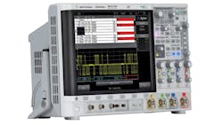
Of course, standards testing with modern oscilloscopes is not reserved for commercial communications systems, and the military has been a longtime user of high-speed oscilloscopes for this purpose. As an example, the MIL-STD 1553 serial bus is largely used in avionics systems for control. It relies on three-level signaling and required dual-level triggering on the test equipment (an oscilloscope) for proper testing. Similarly, the ARINC 429 serial bus is used to interconnect avionics equipment in civilian aircraft. The DSO4XAERO A/D Serial Triggering and Analysis software for the 4000 X-Series oscilloscopes from Agilent Technologies provides eye-diagram masks for both interconnect standards to speed and simplify testing using one of the oscilloscopes (Fig. 3).
In terms of bandwidth and sampling rate, few can match Teledyne LeCroy and its LabMaster 10 Zi series of modular real-time oscilloscopes. Available with four channels at 36 GHz or two channels at 65 GHz, or as many as 80 channels at 36 GHz with additional modules, these oscilloscopes operate at an impressive 160-Gsample/s sampling rate. The LabMaster ChannelSync oscilloscope architecture is built with high-frequency, high-speed SiGe chipsets and timing clocks with extremely low jitter. The sample clock exhibits low jitter of 50 fs RMS while the jitter among measurement channels is held to 130 fs RMS or less.
For those more comfortable with a traditional oscilloscope format, the firm also offers the two- and four-channel HDO4000-MS and HDO6000-MS high-definition oscilloscopes in bandwidths from 200 MHz to 1 GHz (Fig. 4). Rather than plug into external monitors like the LabMaster ChannelSync oscilloscopes, the HDO models all incorporate 12.1-in. touchscreen displays to show signal information captured with a 12-b ADC architecture.
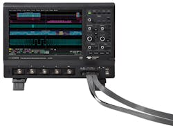
These compact oscilloscopes run at 2.5 Gsamples/s with as much as 25 Mpoints/channel of memory (50 Mpoints/channel when interleaved). They also feature automatic measurements, waveform math, logic-gate emulation, and digital timing measurements. As with many new oscilloscopes, each HDO model is available with a software package that transforms the instrument into a spectrum analyzer, even converting its controls to spectrum-analysis functions. In addition, an optional Power Analysis software package allows an HDO instrument to measure and analyze the operation of power-conversion devices over time.
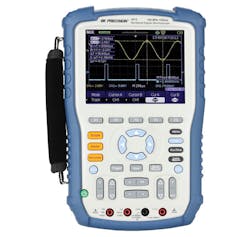
This trend in adding measurement functions even applies to portable, handheld oscilloscopes such as the 2512 from BK Precision (Fig. 5). The dual-channel, 100-MHz-bandwidth miniature oscilloscope features a built-in digital multimeter (DMM) for fast voltage measurements. It also provides a wide range of recording functions, with 3.5 Mpoints of memory per channel or 7 Mpoints of memory for a single channel. The little oscilloscope runs at 1 Gsample/s and shows results on a bright 5.7-in. color display screen. It boasts 32 automatic measurements, including an FFT to make frequency-domain conversions.
Some oscilloscopes are available as PC-based instruments, such as the PicoScope 9300 series from Picotech. The PicoScope 9321 integrates a 20-GHz sampling oscilloscope with a 9.5-GHz optical-to-electrical converter for testing optical communications and other equipment with bit rates to 11 Gbits/s and higher.
“The PicoScope 9300 series are the only compact, full-featured PC-based sampling oscilloscopes on the market. Their specifications and features are a match for traditional full-sized benchtop instruments but at a fraction of the cost,” says Alan Tong, the company’s managing director of market leaders.
The instruments’ 20-GHz bandwidths are aimed at testing high-speed data signals, such as 10 Gb Ethernet, SONET/SDH STM64 and FEC1071, 10x Fibre Channel, InfiniBand, and PCI Express. They offer dual 16-b ADCs with 60-dB dynamic range, 14-GHz trigger bandwidth, and low trigger jitter of 1.8 ps RMS. They rely on updated PicoSample software in 32- and 64-b versions for use with Microsoft Windows XP through Windows 8 and enable 138 automatic measurements and 167 communications standards masks, including spectrum-mode measurements.
In at least one case, a portable oscilloscope is using Wi-Fi to make the test, rather than as the subject of the test. The CarScope PRO PC-based automotive oscilloscope from Ditex Co. is a four-channel wireless automotive diagnostic instrument designed for professional automotive technicians (Fig. 4). Developed for software running on Windows-based PCs, it is connected to an automobile but transfers test data to its controller, a remote computer, by means of Wi-Fi IEEE 802.11b/g (from 2.412 to 2.484 GHz). It serves as an engine analyzer for any vehicle and can operate on a wide range of power sources (8 to 36 V dc).
The use of a high-speed oscilloscope may at times be preferred to a frequency-domain instrument such as a spectrum analyzer for complex communications signals, as is the case with Wi-Fi and LTE signals, but also for signals in possibly emerging ultra-wideband (UWB) communications systems. Such systems, with frequencies allocated from 3.1 to 10.6 GHz and data rates reaching 1024 Mbits/s, will support short-range communications with complex, self-synchronizing, packetized, half-duplex signals.
As UWB applications emerge, characterizing devices using such complex signals may be eased by the measurement capabilities and automated functions of modern oscilloscopes. At least one company, Tektronix, has offered free test software for its oscilloscopes for some time to aid with UWB testing (see “Free Scope Software Aims At USB Testing” at http://mwrf.com/test-and-measurement/free-scope-software-aims-uwb-testing).
This file type includes high resolution graphics and schematics when applicapable.
About the Author
Jack Browne
Contributing Editor
Jack Browne, Technical Contributor, has worked in technical publishing for over 30 years. He managed the content and production of three technical journals while at the American Institute of Physics, including Medical Physics and the Journal of Vacuum Science & Technology. He has been a Publisher and Editor for Penton Media, started the firm’s Wireless Symposium & Exhibition trade show in 1993, and currently serves as Technical Contributor for that company's Microwaves & RF magazine. Browne, who holds a BS in Mathematics from City College of New York and BA degrees in English and Philosophy from Fordham University, is a member of the IEEE.
Comment About the Article
To join the conversation, and become an exclusive member of Electronic Design, create an account today!

Leaders relevant to this article: