What’s The Difference Between ATPG And Logic BIST?
Two test strategies are used to test virtually all IC logic: automatic test pattern generation (ATPG) with test pattern compression and logic built-in self-test (BIST). This article will describe how ATPG and logic BIST work, explain the differences between them, and offer guidelines on when to use one, the other, or a mixture of both.
How Does ATPG Work?
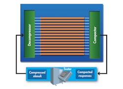
To verify the correct fabrication of digital circuits, test engineers apply patterns from an external tester and observe the results. Larger designs need to use embedded compression to reduce the pattern volume and test time. Compression works by dividing the chip’s scan chains into smaller balanced chains that are connected between a decompressor and a compactor (Fig. 1). The tester patterns are smaller by a couple orders of magnitude, and only a few primary I/Os need to be connected to the external tester.
How Does Logic BIST Work?
Many designs need to be tested or retested in a system or board. For this, you need logic BIST (Fig. 2). A BIST engine is built inside the chip and requires only an access mechanism like the test access port (TAP) to start. When a device is powered on, BIST can also check that the logic is working properly before starting any functional tests.
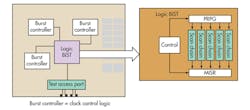
BIST sends out test patterns generated by a pseudorandom pattern generator (PRPG) along scan chains and then collects the responses in a multiple-input signature register (MISR). The final content of the MISR is a signature that determines the pass/fail result. The signature is typically sent out via the TAP and then compared to a pre-calculated, or expected, signature.
Comparing ATPG And Logic BIST
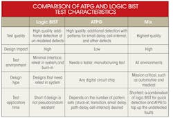
Designs that require very low defects-per-million (DPM) such as those in the automotive space or medical field often specify logic BIST in addition to ATPG tests. Designs with less stringent DPM requirements may be tested with ATPG alone (see the table).
This file type includes high resolution graphics and schematics when applicable.
On the design implementation side, logic BIST has more strict rules that must be followed, while the rules for ATPG are relatively straightforward. For example, any black-box module or non-scan instance is a source of an unknown value, which logic BIST cannot tolerate. During logic BIST, any unknown value in the circuit will corrupt test responses and result in an incorrect signature. These black-box, or non-scan, instances pose no problems to ATPG because deterministic patterns are used to target the faults. Thus, the impact on the designer is higher for BIST than for ATPG.
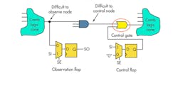
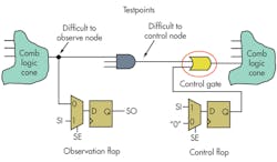
With the pseudorandom patterns used in logic BIST, there are sometimes faults that are difficult to observe and difficult to control. Testing can be improved by adding observe and control test points. Test points may not be necessary for ATPG testing, although in some cases they may help to reduce pattern volume (Fig. 3).
Regardless of your method of testing, multi-cycle paths and false paths in the functional design need to be identified and provided as input during test pattern generation. Typically, these are present in the functional design constraints file, which are read into a tool like Mentor Graphics’ Tessent FastScan to create deterministic patterns. FastScan considers multi-cycle paths and false paths when creating patterns and masks any potential unknown states. To deal with multi-cycle and false paths in logic BIST, hardware circuitry can be automatically added by design for test tools on the source flop of a path to hold its value for the desired number of functional clock cycles.
Synchronous clock domains are treated in a similar manner for both logic BIST and ATPG methods. However, ATPG and logic BIST deal with asynchronous clocks differently. Cross-domain communication via asynchronous clocks may exist in the design, but do not necessarily affect functionality during normal operation. During test, though, this cross-communication may cause inaccurate results.
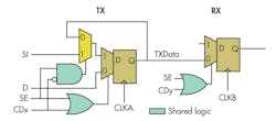
During ATPG, you can specify how to trigger the clocks. But in logic BIST, there is no mechanism to specify how the clocks are triggered. Logic BIST requires special circuitry to handle the source and destination flops. The source flop of a cross-domain clock is held at a constant scan-in value while the destination flop is allowed to capture and vice versa.
Figure 4 shows two flops in different asynchronous domains: CLKA and CLKB. The source flop on CLKA has a multiplexer (shown in dark blue) that holds the scan-in value when the destination flop on CLB captures. The signals CDx and CDy are “one-hot” decoded signals, meaning only one of the signals is active.
Another difference between ATPG and logic BIST is in the area of engineering change orders (ECOs). If an ECO results only in combinatorial logic changes, then with either ATPG or logic BIST, you only need to regenerate the patterns. If the ECO requires the addition of only a few functional flops, then the most straightforward way to handle the new flops with ATPG is to not test them, i.e., to mask them in the pattern. For logic BIST you would need to add circuitry to keep those flops in shift-only mode by holding the scanEnable line high.
Both ATPG and logic BIST can achieve the same level of diagnostic resolution. Mostly, the diagnostics for logic BIST designs are done offline after collecting information on failing signatures. For ATPG, the diagnostics can be done concurrently with production testing. A design implemented with both test techniques can use ATPG for online diagnostics to achieve the desired diagnostic resolution during production test.
Both ATPG and logic BIST support low-power shift, which is attractive for low-power and ultra-low-power design applications. In both cases, there are options to control the percentage of flops that toggle during pattern shift operations.
Differences In Pattern Application/Fault Coverage With ATPG And BIST
The goal of test is to attain maximum coverage using the fewest number of tester cycles. Fewer cycles means less test time and less use of tester memory to store patterns. Designs using ATPG scan patterns require multiple sets of patterns to target known fault models like stuck-at, transition, path delay, small delay, and cell-aware faults. Designs that use logic BIST have a single pattern set to target all types of faults in the circuit.
Logic BIST requires a large number of patterns (in the order of 64k to 150k) to be applied to achieve high stuck-at fault coverage. But the N-detect value, which denotes how many times a specific fault has been detected, is very high with logic BIST (typically 15 or higher), and the N-detect value is directly correlated to defect coverage.
With ATPG, a deterministic pattern set is used to target a specific fault, say, stuck-at or transition faults. These deterministic patterns can be tuned to specific design requirements and compacted and/or compressed. During ATPG, specific dynamic compaction may be used to achieve a smaller external pattern set..
High-transition fault coverage can be achieved with deterministic ATPG, but the patterns needed may be large. Some specific fault sets, like path delay and small delay defect, also can be targeted with ATPG deterministic patterns.
In ATPG, if a particular flop captures a wrong value due to stuck-at or at-speed transition failures, then just that flop can be masked, i.e., not compared. Hence, the fault coverage loss is not severe. In logic BIST, there is no way to mask a single flop. The entire chain between the PRPG and MISR must be masked. The resulting fault coverage can be calculated for the rest of the chains that do capture. The chain masking can be done on the output only or both at the input and output.
Automotive and medical designs are being tested with a combination of both pseudorandom logic BIST patterns and deterministic ATPG. With this hybrid test technique, you can use ATPG to achieve very low DPM and check for small delay, timing-aware, cell-aware, and path delay types of defects. Logic BIST allows the chip to be tested during burn-in and in system.
Because more designs are using a combination of both logic BIST and ATPG, EDA vendors now provide tools to reuse logic between ATPG embedded compression and logic BIST. Designs that require both ATPG compression and logic BIST can share the PRPG and compactor circuitry, reducing on-chip hardware cost of test. Hybrid testing can also achieve reduced test times by testing some cores with compressed patterns while running logic BIST on other cores in parallel.

About the Author
Vidya Neerkundar
Technical Marketing Engineer
Vidya Neerkundar obtained her MS in electrical engineering from Wright State University, Dayton, Ohio, and now is a technical marketing engineer in the Silicon Test Solutions group at Mentor Graphics Corporation.
Comment About the Article
To join the conversation, and become an exclusive member of Electronic Design, create an account today!

Leaders relevant to this article: