What’s The Difference Between A Mixed-Signal Oscilloscope And A Logic Analyzer?
Logic analyzers and oscilloscopes have coexisted for several decades. The emergence of additional digital inputs on scopes more than 15 years ago gave birth to mixed-signal oscilloscopes (MSOs). Once a niche product category, MSOs now are offered by all major scope vendors. Many of these scopes include mixed-signal capabilities. Logic analyzers continue to be offered by major test and measurement vendors as well. While some engineers regard MSOs as narrow-channel logic analyzers, the difference between the product types is more substantial.
>> Download the .PDF version of this article and learn more about oscilloscopes
Which Instrument Is Home Base?
After using logic analyzers extensively for 15 years, I’m extremely comfortable setting up logic analyzers; acquiring signals and buses from a variety of FPGAs, ASICs, microprocessors, and state machines; and working with logic analyzer probing. Logic analyzers are great for tracking down functional and timing problems. A job change resulted in me getting my first MSO in 2005. I became a fan and now have extensively used seven different MSOs from a variety of scope vendors.
A key difference between logic analyzers and MSOs is that you can use an MSO simply as a scope, which is how one would use it most of the time (see the table). When needed, MSO digital channels provide just enough logic analysis for users whose home base is a scope. MSO digital channels are an extension to the scope. Digital channels can lie dormant for long periods until the need for them arises. This seems obvious, as the primary value of the MSO is the scope, not the digital channels. Once you have thought this through, your thinking about MSOs and logic analyzers becomes more rational.
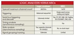
While logic analyzers are typically used for single-shot applications, MSOs work across both single-shot tasks and applications that require the viewing of repetitive waveforms. MSOs have a simpler use model, as they’re usually limited to 16 channels or less, while logic analyzers come with many more channels. This limits MSO debugging to tasks that can be solved with up to four analog scope channels plus up to 16 digital channels, while logic analyzers can be used on debug tasks that require anywhere from a single channel up to hundreds of channels. That’s why users often think logic analyzers are more complex than MSOs.
While logic analyzers offer up to hundreds of time-aligned channels, the overlap with MSOs is really for users of logic analyzers with 34 or 68 channels. Users often will employ only a fraction of logic channels in debugging. They also can use additional channels to monitor parallel events that require a great number of channels.
State And Timing Analysis
MSOs and logic analyzers have fundamental architectural differences in how they acquire and display signals. MSOs exclusively use asynchronous sampling, just like an oscilloscope. For many users, this makes setting up an acquisition on digital channels simpler, because it feels like a scope. There is no need to know the difference between timing and state analysis or to specify a clock signal. MSO users get responsive updates when running repetitively.
In contrast, logic analyzers offer more extensive acquisition modes with both timing and state analysis. State analysis is a great way to capture data on synchronous buses that have a clock. State captures only occur on valid clock conditions, which eliminate the capture of unimportant transition activity between valid clock signals. They also increase the width of the captured time window by using logic analyzer memory only when valid states occur. Optimized for capturing and displaying single-shot events, logic analyzers suffer from long stretches of dead time between acquisitions when running repetitively.
Interestingly, logic analyzer users typically find grouping and naming signals and buses to be much simpler on a logic analyzer than on an MSO. Ironically, MSO users typically find logic analyzer grouping to be more complex.
Triggering
MSOs and logic analyzers differ greatly in their triggering capabilities. Triggering in an MSO’s digital channels parallels its analog triggering. Most MSOs include both edge and pattern triggers, as well as the ability to combine these trigger conditions. Additionally, many vendors allow digital channels to be used for pulse-width and other time-based triggers. Triggering typically extends across both MSO digital and analog channels so users can trigger on a bus pattern on digital channels when a clock on an analog channel goes high.
As logic analyzers have no scope channels, users must team them with a standalone scope with a more complex cross-triggering setup to come close to triggering and measuring across analog and digital domains.
MSOs are generally architected with a single-stage trigger (one event), while logic analyzers incorporate sequential triggering. Logic analyzers allow the specification of a sequence of events that must occur in that sequence before the analyzer makes an acquisition.
Some scopes offer sequential triggering. However, the multiple stages are limited strictly to analog channels and are less capable than logic analyzer trigger sequencers. For example, logic analyzer sequences give users eight or more stages with storage options at each stage. MSO triggering is typically limited to a single pattern or a combination of edges and patterns with none of the logic analyzer trigger sequencing storage options on each level.
Low-Speed Serial Bus Support
A key difference between logic analyzers and MSOs is the latter’s ability to trigger on and decode serial buses. Low-speed serial buses are ubiquitous in electronic designs because of their ease and low cost of implementation. It is hard to find a design that does not include at least one I2C or SPI bus, an RS-232 port or another UART standard, CAN, LIN, or USB.
As ball-grid array (BGA) packaging and dense printed-circuit boards (PCBs) limit signal access, serial buses often provide key debug insight. Was my FPGA configured correctly? Do I have an enumeration issue? Can I write and read back from my memory subsystem?
MSOs excel at debug that includes low-speed serial buses. All good MSOs come with both triggering and decode options for serial buses. However, logic analyzers have not incorporated similar triggering and decode technology.
Without protocol triggering, it’s impossible to set up the scope to trigger on specific packets. For example, users can set the MSO to trigger when an I2C read to a certain address with a certain data value happens. Alternatively, users can trigger on a certain SPI data packet or at the start of USB enumeration.
Quality MSOs decode packets at the protocol level. Not only does this save time compared with decoding the packets by hand, it also eliminates errors in protocols such as JTAG, USB, and FlexRay that use complex state machines and/or embedded clocks that make hand-decoding impossible.
Because MSOs include both analog channels and digital channels, it is important to note that the scope channels also can be used for serial bus triggering and decode. It’s often useful to reserve the analog channels for simultaneous examination of system events, though, or to use a combination of analog and digital channels for serial triggering and decode.
For example, one might use an analog channel for monitoring a JTAG clock while connecting four digital input channels to the other signals required for JTAG decode. Or, for four-wire SPI, a combination of analog and digital channels frees up at least one analog channel to simultaneously view other signals.
Probing And Supported Signal Types
Most mainstream logic analyzers and MSOs support single-ended signals and have threshold and minimum signal-swing requirements of about 500 mV to differentiate between ones and zeros. Signal access tends to be better thought out for logic-analyzer users due to the increased number of expected channel connections, while digital channel MSO probing tends to be an afterthought with no special built-in connectors.
Some MSOs offer Mictor, Samtec, and connectorless probing, but the dominant use mode continues to be connection using flying leads. Mainstream logic analyzers use similar flying-lead technology, as well as connector-based and connectorless probing.
To produce affordable MSOs, vendors build MSO digital-channel probes, cables, and front ends with limited analog bandwidth (typically 300 MHz to 500 MHz) and uniquely offer single-ended signal support. The analog-bandwidth limitation can confuse users who see MSO sample rates (typically called out as a banner spec) far in excess of the digital-channel bandwidth (typically not called out as a banner spec), believing that this leads to greater measurement precision.
In reality, the upper-frequency components of incoming signals are attenuated and will not make much difference in the accuracy of measurements. More expensive high-end logic analyzers and MSOs incorporate front-end technology and probing to support differential signals and high-bandwidth probes and cables. These tools typically support bandwidths in excess of 2 GHz, allowing these products to better use faster sampling rates.
Cost of a New Oscilloscope
It is extremely rare for a design team to be torn between purchasing a logic analyzer or an MSO. Rather, for an engineer or team needing a new scope, the addition of MSO digital channels can be attractive. Typical incremental cost is $2000 to $4000 on top of the scope. Most scope vendors offer scopes that can be upgraded to MSOs with a license key, an MSO cable, and probes. Upgrading to an MSO is quick and easy.
There are instances, though, when a team has a limited budget and must determine whether a scope or logic analyzer is a bigger need. The MSO really plays a secondary role behind the scope. As expected, 34- and 68-channel logic analyzers tend to be slightly more expensive than 16-channel MSOs, as they’re more capable for issues that require additional channels, state analysis, and easier grouping and naming of signals and buses.
While a scope can be upgraded later to add MSO digital signals, logic analyzers don’t offer the ability to upgrade to add scope analog channels. At the very high end, 16-channel MSOs cost in excess of $10,000, making them more expensive than a mainstream 68-channel logic analyzer, but less expensive than a 68-channel high-speed logic analyzer with differential signal support.
MSOs have become widely popular over the last few years. Pioneered and first invented by HP, now Agilent, they now are offered by every scope vendor. The value of MSOs over DSOs lies in their complement of 16 digital channels when the need arises to view state machines signals and buses, especially serial buses, where the scope’s four analog channels aren’t sufficient. With the continual migration of parallel buses to serial, logic analyzers will remain an important tool for users who need state analysis, sequential triggering, and advanced multi-channel probing connections.
References
Learn More About Oscilloscopes

About the Author

Joel Woodward
Oscilloscope Product Planner
Joel Woodward is strategic planner for oscilloscopes at Rohde & Schwarz. He has worked in the test and measurement industry for 27 years. Joel holds a degree in electrical and computer engineering from Brigham Young University, an MBA from Regis University, has completed course work at the Harvard Business School, and holds an FPGA debug patent. His outside interests include digital photography and hiking in national parks.
Comment About the Article
To join the conversation, and become an exclusive member of Electronic Design, create an account today!

Leaders relevant to this article: