Bicolor LED Indicates Voltage Readings Via Visual Pulses
This file type includes high resolution graphics and schematics when applicable.
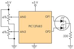
The circuit in Figure 1 uses a bicolor (red/green) LED to indicate the voltage measured with a set of three color pulses. The green, yellow, and red pulses indicate the units, decimal point, and decimals of volt, respectively.
The circuit is based on the 8-pin MCU PIC 12F683. It requires only two I/O lines to display a voltage reading with a resolution of 0.1 V. The period of the LED pulses can be adjusted from 1 to 255 ms with the trimming potentiometer (trimpot) connected on AN3. With this trimmer, users can set the refresh rate to suit their needs. The software program occupies only 280 words out of the 2 kB of available program memory.
The input voltage range measured on pin AN0 ranges from 0 to 5.00 V dc and the total current consumption is 5 mA, with precision of ±19.6 mV. A trimpot connected to that analog input is used to read an input voltage, and the second trim pot connected to AN3 adjusts the period of the pulses to users’ needs. To save energy, the analog-to-digital converter is turned off between each reading.
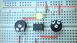
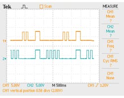
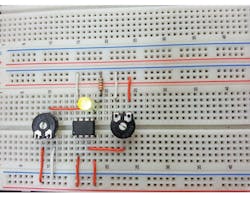
Figure 2 shows a set of train pulses in the scope for a voltage reading of 2.4 V. Notice that the two pulses on the top line represent two volts (green LED), then a single pulse in the middle indicates the decimal point (yellow color), and the bottom line has five pulses (red LED). Figure 3 shows the physical circuit assembled on a prototyping board.
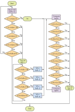
The algorithm provided in the flowchart (Fig. 4) is based on PIC Basic Pro Compiler (see the listing below). It starts by measuring the input voltage to detect its range with five magnitude comparisons for the volt’s units. There are five different ranges for the full scale of five volts. If the voltage is less than 1 V, for example, the yellow LED will pulse the decimal point, then the red LED will display the decimal value of the voltage with the corresponding number of pulses. Once the unit’s voltage range is detected, the program makes 10 comparisons to find the range in 100-mV increments. In this way, it will generate the correct number of pulses for the decimal value of volts.
The energy efficiency and compact size of this design suit it for diverse applications. It can be used to represent other variables using the PWM code in the microcontroller. In this case, the PWM can drive an LED in multiple ways by controlling its duty cycle and, therefore, the power dissipated. In addition, it can transmit a reading with a pair of LEDs (transmitter/detector) to monitor an input voltage at a limited distance.
Software program for the PIC MCU to indicate a voltage with a bicolor LED:
****************************************************************
'*  Authors  : Ricardo Jimenez and Kimberly D. Varela                       *
'*  Date    : 3/25/2014                                                *
'*  Version : 1.0, based on PIC 12F683 with internal oscillator set to 4 MHz      *
'*  Notes   :   Range: 0-5 Vdc, Resolution: 0.1V, Precision: +/20 mV          *
'****************************************************************
VOLT Var BYTE:I VAR BYTE: N VAR BYTE: V2 VAR BYTE: N1 var byte: V1 var byte; 8-bit variables
OSCCON = %01100101: OSCTUNE = 0 ; Internal oscillator set to 4mHz
TRISIO = %00011001   ;I/O,(GPIO.3 default), INPUT: GPIO.0, GPIO.4
ANSEL =  %00010001   ;Analog INPUTS: GPIO.0, GPIO.4
CMCON0 = %00000111   ;Comparator disabled
DEFINE ADC_BITS 8    ;A/D Resolution set to 8 bits
DEFINE ADC_CLOCK 3   ;A/D using internal RC oscillator
DEFINE SAMPLEUS 50   ;Acquisition time 50 uS
GPIO=0                 ; Clearing port
RPT:                 ; Starting Label
N= 0: volt=0: N1=0; Variable N=0, N1=0, VOLT=0
  ADCIN 0, VOLT;      Read voltage measurement on AN0 and save it in variable VOLT
  ADCIN 3, V1    ;    Read voltage on AN3 and save it on V1 variable to adjust pulse periods
  ADCON0.0=0;    ;ADC OFF
  IF (VOLT >=%00000110) AND (VOLT <=%00110011) THEN TH;     Range 0.108V to 0.987V
  IF (VOLT >=%00110100) AND (VOLT <=%01100110) THEN INT;   Range 1.015V to 1.983V
  IF (VOLT >=%01100111) AND (VOLT <=%10011010) THEN INT2; Range 2.003V to 2.999V
  IF (VOLT >=%10011011) AND (VOLT <=%11001111) THEN INT3; Range 3.018V to 3.984V
  IF (VOLT >=%11001101) AND (VOLT <=%11111111) THEN INT4; Range 4.003V to 4.978V
  goto RPT
TH:         ; Label for tenths
     v2= 0     ; Clear V2 variable
     PAUSE V1;    pulse period set by trim pot
     GPIO.1= 1;    The output GPIO.1 is equal to one
     GPIO.2= 1 ;   The output GPIO.2 is equal to one
     PAUSE v1   ;
     GPIO.1= 0  ;The output GPIO.1 is equal to zero
     GPIO.2= 0  ;The output GPIO.2 is equal to zero
     PAUSE v1   ;Pause

     if  volt <= %00110011 then TH1; If voltage >=0.987V, go to TH1 label
 IF (VOLT >= %00110100) AND (VOLT <=%01100110) THEN TH2 ; Range  1.015V to 1.983V
 IF (VOLT >= %01100111) AND (VOLT <=%10011010) THEN TH3 ; Range of 2.003V to 2.999V
     IF (VOLT >= %10011011) AND (VOLT <=%11001111) THEN TH4 ; Range of 3.018V to 3.984V
     IF (VOLT >= %11001101) AND (VOLT <=%11111111) THEN TH5 ; Range of 4.003V to 4.978V
TH1:            ;
     V2= VOLT: GOTO COMP; Voltage less or equal than 0.987, saved in V2 variable and go to COMP label
TH2:            ;
  V2= volt - %00110100: goto COMP;     Subtracting VOLT - 1.015V
TH3:                   ;
     v2= volt - %01100111: goto COMP;       Subtraction: VOLT - 2.003V
TH4:            ;TH4 Label
 v2= volt - %10011010: goto COMP;       Subtraction: VOLT - 2.999V
TH5:            ;TH5 Label
 v2= volt - %11001101: goto COMP;       Subtraction: VOLT - 4.003V
COMP:           ;                     Label for comparison of tenths
  N1= 0         ;Clear N1
  if (v2 >=%00000101) and (v2 < %00001011) then n1=1: goto TH6 ; Range of 0.097V to 0.206V
  if (v2 >=%00001011) and (v2 <=%00001111) then n1=2: goto TH6 ; Range of 0.206V to 0.284V
  if (v2 > %00001111) and (v2 <=%00010100) then n1=3: goto TH6 ; Range of 0.284V to 0.390V
  if (v2 > %00010100) and (v2 <=%00011010) then n1=4: goto TH6 ; Range of 0.390V to 0.499V
  if (v2 > %00011010) and (v2 <=%00011111) then n1=5: goto TH6 ; Range of 0.499V to 0.596V
  if (v2 > %00011111) and (v2 < %00100100) then n1=6: goto TH6 ; Range of 0.596V to 0.703V
  if (v2 >=%00100100) and (v2 < %00101001) then n1=7: goto TH6 ; Range of 0.703V to 0.800V
  if (v2 >=%00101001) and (v2 <=%00101111) then n1=8: goto TH6 ; Range of 0.800V to 0.909V
  if (v2 >=%00101111) and (v2 <=%00110011) then n1=9: goto TH6 ; Range of 0.909V to 0.987V
  GOTO RPT
INT4: N = N+1   ; Labels for the corresponding value of integer N
INT3: N = N+1   ;
INT2: N = N+1  ;
INT1: N = N+1   ;
  FOR I = 1 TO n    ; FOR cycle for integers
  GPIO.2 = 1    ;    output GPIO.2 is equal to one
  PAUSE V1      ;  Controlled  pause by V1 variable
  GPIO.2 = 0    ;   The output GPIO.2 is equal to zero
  PAUSE V1      ; Controlled pause by V1 variable
  NEXT I         ;Jump to next FOR cycle
  PAUSE V1      ; Controlled pause by V1 variable
  goto TH       ;     Go to TH label
TH6:            ;       TH6 Label
  FOR I = 1 TO N1  ; loop for tenths
  GPIO.1 = 1       ; output GPIO.1 is equal to one
  PAUSE V1      ; Controlled pause by V1 variable
  GPIO.1 = 0     ;  output GPIO.1 is equal to zero
  PAUSE V1      ; Controlled pause by V1 variable
  NEXT I           ; Jump to next FOR cycle
  PAUSE V1      ;Controlled  pause by V1 variable
  GOTO RPT      ;Go back to RPT label
END
Ricardo Jiménez holds a master’s degree in electronics from ITM. He is an adjunct professor at Imperial Valley College, Imperial, Calif., and at ITT-Tech in Vista, Calif. He can be reached at [email protected].
Kimberly D. Varela holds an electronics engineering degree from ITM.
This file type includes high resolution graphics and schematics when applicable.
