This file type includes high-resolution graphics and schematics when applicable.
During the design phase of a battery-powered product, engineers will need to qualify cells for suitability in the application. This testing often is done with dedicated cell test equipment, but sometimes engineers will turn to standard off-the-shelf power supplies to charge the cells and standard off-the-shelf electronic loads to discharge the cells.
Such standard power test equipment, easily found in R&D labs, can be more flexible than dedicated cell testers. That’s because you can program standard power supplies and e-loads to provide a wide variety of charging and discharging profiles to meet specific application needs.
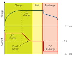
Let’s look at using a standard power supply for the charge step of a typical charge/discharge cycle for a lithium-ion cell (Fig. 1). The charge begins with the power supply programmed to the desired cell charge current and operating in constant current (CC). As the cell begins to charge, it in turn ramps up the voltage on the cell. Then, as the charge step progresses, the cell will be charged up to the cell’s open-circuit voltage.
At that point, the power supply will hit its programmed voltage limit (which would be programmed to the cell’s open-circuit voltage) and then begins operating in constant-voltage (CV) mode. Once in CV mode, the current out of the power supply into the cell will begin to drop off and the voltage will stay constant on the cell.
You will want to terminate the charge step when the charge current drops to below some predetermined cutoff value. For example, if you were charging a large cell, perhaps for an automotive application, if the maximum charge current is 20 A, the cutoff might be 50 mA. Now, when the cutoff value is reached, the cell is considered fully charged, the charging should stop, and the cell charge/discharge cycle will proceed to the next step, which is typically some rest period.
First, let’s think about what instrument will make the measurement of the cell charge current. Since we’re talking about high current charging, measuring the current with an ammeter may not be practical, as the maximum current may exceed a typical DMM’s current rating. So let’s assume you’re using the power supply’s built-in current measurement to measure the charge current. We’ll come back to this later.
As mentioned above, to terminate the charge step, the current is measured and compared to a cutoff value. Should the current measurement be noisy, it will be difficult to determine the right moment to cut off the charge step. This cutoff current threshold will be a low current value compared to the maximum charge current, meaning you have to measure current over a wide dynamic range. Consequently, noise can be a real problem at the low end.
Recall that we’re talking about a large cell with a maximum charge current of 20 A and a cutoff of 50 mA. If you experienced 100 mA of noise at full charge current of 20 A, this would be 0.5% measurement error due to noise, which is perhaps tolerable. However, that same 100 mA of noise will obscure the 50-mA cutoff, making it hard to determine the right time to stop charging.
Understanding the Current-Measurement Noise Source
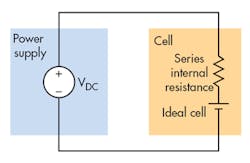
Let’s look at the test setup (Fig. 2). In this very simple setup, the power supply is connected to the cell that needs to be charged. The cell is often modeled as an ideal cell with an internal resistor in series. This series resistance can be measured using an ac resistance (ACR) measurement on dedicated cell test equipment, or an LCR meter.
Cell internal resistance will be in the range of tens of milliohms for high current cells, to hundreds of milliohms for smaller cells, to one or more ohms for really small cells, such as button cells. But in this example, we have been talking about high current cells, so let’s continue by assuming we have tens of milliohms of internal resistance.
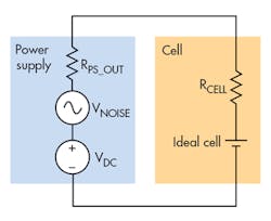
The power supply that’s charging the cell will have voltage noise on its output. A reasonable specification for voltage noise is 10 mV p-p on a 10-V power supply. Figure 3 depicts simple models for the cell and for power supply, showing the impedances and noise sources. At frequencies below 100 Hz, RPS_OUT will be virtually 0 Ω. The power supply’s output-voltage noise appears as an ac voltage source in series with the dc output. That ac voltage (the noise) will appear as an ac current across the very low ohm series resistor in the cell, courtesy of Ohm’s Law: INOISE = VNOISE / (RPS_OUT + RCELL).
So the noise on the current measurement isn’t measurement noise. Rather, it’s real current noise due to the power supply’s output-voltage noise appearing as current through the cell’s internal series resistance. Even a low-noise power supply can end up creating current noise on the cell when the cell’s internal resistance is so low.
Methods for Resolving Cutoff Current
To determine when the charging has reached the cutoff current in face of the induced current noise, the easiest solution is to average the measurement. By applying a long measurement integration time of a few seconds, or even one minute, to the current measurement, this ac noise component will be averaged out. This will give you a stable dc value to measure and compare against the cutoff threshold.
But what if the power supply doesn’t have programmable-current-measurement integration time? In this case, you could make several measurements and bring them into a computer, average them together, and use the average to determine if you have reached the cutoff current.
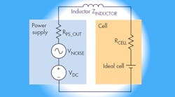
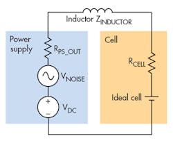
Another method would be to use an inductor in series with the cell (Fig. 4). The inductor will have low impedance at low frequency and a higher impedance at higher frequencies. Again, using Ohm’s Law, where INOISE = VNOISE/(ZPS_OUT + ZINDUCTOR + ZCELL), as frequency goes up, ZINDUCTOR goes up and dominates the denominator. Thus, the current noise (INOISE) drops off with increased frequency.
The inductor, therefore, will create a low-pass filter and attenuate the noise as you look at higher frequencies. This will clean up the noise, enabling you to better determine if you have reached the dc cutoff current. Ideally, that filter will cut off below 10 Hz to greatly reduce the induced noise currents near dc. Assuming 20 A of charge current and a cell series resistance of 10 mΩ, the inductor would need to be hundreds of microhenries.
Note that the inductor will need to be able to carry the full dc charge current of 20 A, so this will not be a small, surface-mounted component. However, it’s quite feasible to hand-wind a wire around a toroidal core to make a suitable inductor.
Looking for parts? Go to SourceESB.
