How to Pick the Right Oscilloscope Probe
This file type includes high-resolution graphics and schematics when applicable.
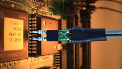
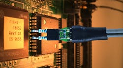
Literally hundreds of different oscilloscope probes are available (Fig. 1), so how do you choose the right one? There’s no single answer because all designs are different. To help in the decision-making process, here are some different probe characteristics you’ll want to consider.
Bandwidth Is Important
A probe’s bandwidth is typically its banner specification. It essentially describes how high of a frequency the probe is able to pass on to the oscilloscope. Before investing in a new probe, you should consider the speed of your signal’s frequencies. As a rule of thumb, your probes should be at least three to five times faster than the fastest signal you want to see.
Consider the Attenuation Ratio
Probes have different (sometimes switchable) attenuation ratios that change how the signals are fed into your oscilloscope. For example, a 10:1 probe connected to a 1-V signal will pass 100 mV to the scope’s input. The scope will read the probe’s attenuation ratio and display the correct signal values on the screen so that you needn’t do the calculations in your head.
Having a higher attenuation ratio (100:1, 1000:1) will allow you to look at higher voltages, but it will also make the scope’s internal amplifier noise more pronounced. The higher the attenuation ratio, the more scope noise you’ll see. For example, a 10:1 probe will show 10X the noise. This might lead you to believe that you should always use a 1:1 probe. Not true! Lower attenuation probes typically have much higher loading on your system, which brings us to the next probe characteristic to consider.
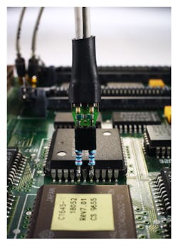
1. A probe at work on a chip.
Probe Loading
Connecting anything to your device under test (DUT) will change the inherent electrical characteristics of your system. Despite our best R&D efforts, probes are still subject to the laws of physics. (If we get around this pesky barrier, we’ll be sure to let you know!) So, any time you are probing your system, it will affect your device. Unnecessarily loading your system can lead to inaccurate measurements and even change the shape of the waveform on your oscilloscope screen!
Probing loads aren’t just resistive, either; they have inherent capacitive and inductive effects. Capacitive effects are generally the most difficult to work with and are extremely responsive to frequency. Too much capacitive loading will slow down your system’s bandwidth, effectively slowing down your signal’s rise and fall times. If rise/fall times slow down too much, you’ll start seeing bit errors in your system.
As a general rule, the higher the attenuation ratio of the probe, the lower the capacitive loading. So a 1:1 probe may not be the best choice. Oftentimes, 1:1 probes have capacitive loading somewhere around 100 pF, while a 10:1 probe is typically in the range of 10 pF. So even though a 1:1 probe helps reduce your oscilloscope amplifier noise, there’s a tradeoff.
Higher-end scopes often use digital signal processing (DSP) to help compensate for probe loading, but it’s simply impossible to eliminate probe loading altogether. Therefore, make sure the probes you pick have impedance values that will fit into your design parameters.
Another way to help reduce probe loading is to use an active probe.
Active Versus Passive Probes
Many engineers will only consider an active probe if they need to look at high bandwidths. However, the probe loading from active probes is significantly lower than that of passive probes. By designing a high-frequency amplifier into the probe head, the probe cable and oscilloscope front end are isolated from your DUT. This can bring the probe loading down to 1 pF or better.
What does this mean for your measurements, though? Let’s look at a system with a 1.1-ns rise time. Conventional wisdom would tell you that you only need around 300 MHz of bandwidth. Use the formula:
Required Bandwidth = 0.34/rise_time
So we set up our system and measure our edge with an active probe, and see a 1.1-ns rise time. We then disconnect the active probe and connect the free-with-the-scope 500-MHz passive probe. Subsequently, we measure the rise time and see it has changed to 1.5 ns. What happened? The passive probe’s capacitance is adding more load to our system, and it’s having trouble driving the extra load. The extra load from the probe is distorting the device’s signals! The difference in measured edge speeds can be clearly seen in Fig. 2.
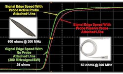
2. Shown is the difference in measured edge speed using an active versus a passive probe.
So, should I ever use the passive probes that come with my oscilloscope? Yes! Passive probes are great for qualitative measurements (i.e., checking clock frequencies, browsing for bugs, etc.). But, active probes excel in quantitative measurements like output ripple or rise times. While active probes cost more than passive probes, they can make a big difference in measurement accuracy.
If you want to know how much your probes are loading your system, you can double-probe your DUT. First, connect one probe to a known step signal on your DUT (or as close as you can get). Observe and/or save the waveform on the screen. Then, leaving the first probe connected, connect a second probe to the exact same spot and observe the change in your edge speed.
Probe Compensation Range
Probe compensation makes it possible to adjust the impedance of your probes to fine-tune your acquisition system. The input impedance of an oscilloscope can vary from model to model, and even from channel to channel, due to differing component values.
Passive probes typically come with an adjustable input impedance that allows you to impedance match your probe and scope. This ensures that your probe will perform as expected for its rated bandwidth. The probe’s impedance can usually be adjusted on your probe using a small (included) screwdriver. Figs. 3, 4, and 5 give examples of what an under-, over-, and properly compensated probe looks like:
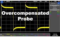
3. This screenshot indicates an overcompensated probe; the signal should be a square wave.
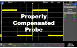
4. Here's what a properly compensated probe should look like.
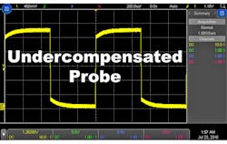
5. This screenshot indicates an undercompensated probe; the signal should be a square wave in this case, too.
All of these screenshots are using an identical probe and signal; only the probe compensation has changed.
Your oscilloscope will have a “typical” input capacitance value, and you want to make sure that your probe’s compensation range can match. If your probe can’t fully compensate for your scope, you will get sub-par measurements, especially when measuring higher frequencies.
Connecting to Your Device
Another consideration when evaluating probes is how you will physically connect to your system. For low-frequency measurements, the grabber-hat on your passive probe might be good enough. But, as system bandwidth increases, you’ll need to look at other options.
Can you use a ZIF tip, an SMA probe head, a solder-in probe head, or my favorite: the N2848A magnetic QuickTip head? Such questions are beyond the scope of this article, but essential to engineers needing to look at fast signals. Make sure you are designing boards that can be probed, and selecting probes that will provide a good connection to your board. The length of your ground lead is also an important part of connecting to your device, because it can act as an antenna.
Signal-Dependent Probing
Lots of different styles of probes are available, depending on what signals you’re probing. The type of signal can significantly narrow down your probe choices. Are your signals differential? Use a differential probe and eliminate common-mode noise. Measuring current? Use a current probe instead of a sense resistor and a voltage probe. Measuring extremely high voltages? Don’t risk your life and use a high-voltage probe with its extra high attenuation ratio.
Other Probe Considerations
It’s worth noting that your entire acquisition system’s bandwidth is important, not just that of your probe. Your oscilloscope’s bandwidth and probe’s bandwidth both affect total system bandwidth according to the following equation:
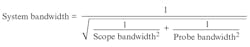
Say you had a 200-MHz scope and used a 200-MHz probe. Your system bandwidth would be roughly 141 MHz.
Also, probes typically come with a probe accessories kit. Before ordering, it’s important to know what is or isn’t included.
Closing Thoughts
Many types of probes are available for nearly every signal you’d want to measure. To avoid confusion, stick to the basics: bandwidth, attenuation ratio, and loading. Fully understanding these specs will help guide you through the many options and help you pick the right probe.
Read More About Oscillosopes


About the Author

Daniel Bogdanoff
Oscilloscope Product Manager
Daniel Bogdanoff is the Product Manager for the InfiniiVision series of oscilloscopes at Keysight Technologies. He graduated from Texas A&M with a degree in electrical engineering. In his spare time, Daniel enjoys whitewater kayaking, mountain biking and playing various musical instruments.
Comment About the Article
To join the conversation, and become an exclusive member of Electronic Design, create an account today!

Leaders relevant to this article: