Oscilloscope Triggering Advanced Course: Advanced Trigger Modes, Part 1
This file type includes high-resolution graphics and schematics when applicable.
Welcome to the Oscilloscope Triggering Advanced Course! In this series, I will walk you through the details of every corner of real-time oscilloscope trigger systems, and by the time we’re done, you’ll never need that AutoScale button again! Your co-workers will be stuck in the lab staring at auto-triggers all weekend while your scope is catching glitches and protocol packets automagically and emailing you the results!
We’re going to start off by talking about advanced trigger modes. These are the different operational modes you choose first when setting up your trigger, with each mode having different options. Broadly speaking, most advanced trigger modes fall into three categories—pulse modes, pattern modes, and edge modes—and we’ll discuss each in detail. In this article, I’ll focus on the pulse and pattern modes. Ready to get started?
Pulse Modes
Pulse-based trigger modes are the most commonly used modes other than regular old edge trigger. They’re all based around the idea of one rising and one falling edge on the same input channel, typically with a time parameter relating the two. Modern scopes typically offer a handful of pulse trigger modes, the most common being:
• Pulse Width (sometimes just called “Width”)
• Glitch
• Runt
While other advanced modes involve time parameters and rising and falling edges, the key take away here is that pulse-based modes are concerned with exactly one rising edge and exactly one falling edge, in a particular order, with both edges occurring on the same input channel. Let’s take a closer look at each of these pulse modes.
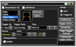
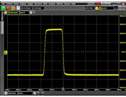
Pulse-Width Mode
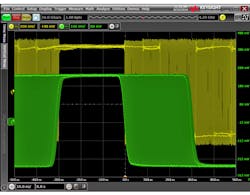
The most common and multipurpose of the pulse modes is Pulse Width (or just “Width” on some scopes), the great grandaddy of the pulse-based modes. In Pulse Width mode, the user specifies the input channel, the pulse polarity (positive or negative), a vertical threshold, at least one time parameter, and at least one parameter that describes how the time parameter(s) should be used to qualify incoming pulses based on their widths. That is, they need to be greater than the time parameter, less than the time parameter, or even greater than one time parameter and less than a second time parameter.
Some scopes also allow the user to setup Pulse Width mode to trigger when a pulse width is equal to or not equal to a specific time value, as well as specify a tolerance for that value. Let’s look at a couple of examples:
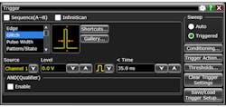
Glitch Mode
Remember how I mentioned above that Pulse Width trigger mode was the great grandaddy of all pulse-based trigger modes? Well, in the case of Glitch mode, the apple fell very close to the tree. Glitch mode is literally just Pulse Width mode with the less-than time condition locked in. That’s it!
Runt Mode
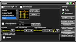
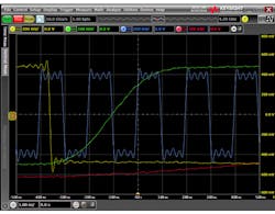
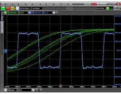
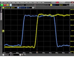
Unlike Glitch mode, Runt trigger mode is functionally different than Pulse Width mode. For the uninitiated, a “runt” in a signal is a pulse that doesn’t fulfill some aspect of its dc specification. In practice, this means that it doesn’t rise as high or fall as low as intended.
Runts can cause all sorts of problems in your circuit, and finding them without a specialized trigger mode can be quite a challenge. Fortunately, you don’t have to do that. In Runt mode, the user specifies an input channel, a pulse polarity, and two vertical thresholds. To be considered a runt that causes a trigger, the signal from the input channel must pass through one of the thresholds in one direction and then pass through the same threshold in the opposite direction without passing through the second threshold in between. In addition, most scopes allow the user to add a time qualification so that the scope will only trigger on runts with a minimum width or greater.
Let’s take a look at two examples:
Pattern Modes
Pattern-based trigger modes are concerned with various events on different input channels occurring, or not occurring, at the same time. The most common pattern-based advanced trigger modes are:
• Pattern
• State
• Setup and Hold
The key takeaway with pattern-based modes is that the trigger event is based on actions coming from more than one input channel at once. Let’s take a closer look at each of them.
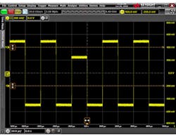
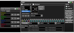
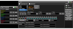
Pattern Mode
Pattern trigger mode is exactly what it sounds like: The scope will only trigger when a certain set of conditions (the “pattern”) is true. The simplest variants of pattern mode will trigger when a pattern is “entered” or “exited.” In other words, the scope will trigger either the instant that all pattern conditions become true when they were previously false, or the instant they become false when they were previously true.
Pattern mode also typically has timed options. For instance, it triggers when the specified pattern is true for greater than a certain amount of time, less than a certain amount of time, or greater than one time parameter and less than a second time parameter.
With respect to defining the pattern itself, typically this just means specifying “high,” “low,” or “don’t care” for each of the available input channels. In this case, “high” and “low” refer to the signal being either above or below a specified threshold for that channel. Some scopes will also include digital channels in the pattern definition and allow the user to configure a trigger that mixes analog and digital inputs. Note that in the case of pattern mode, the specified pattern doesn’t contain any edges. A pattern relative to an edge is actually considered state trigger mode (we’ll look at that next).
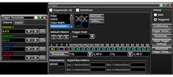
State Mode
Similar to pattern mode discussed above, state trigger mode allows the user to define a pattern of high/low/don’t care input channels. Unlike pattern mode, state mode requires the user to include exactly one edge in the pattern definition. In state mode, a trigger will be generated when the specified edge is detected and the pattern is either present (AND logic) or not present (NAND logic), depending on a selectable logic mode parameter. There are often no timed options in state mode.
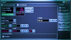
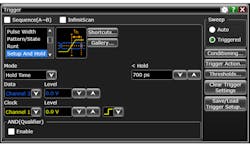
Setup and Hold
Setup and Hold trigger mode is designed to catch—you guessed it—setup and hold violations. It allows the user to specify two input channels—one for clock and one for data—as well as the active clock edge (rising or falling), at least one time parameter, and in some cases, the specific violation you’re looking for (setup, hold, or either).
Like state mode, the trigger point will occur on the specified clock edge. Unlike state mode, Setup and Hold mode can only analyze two input channels and the trigger condition is the setup time, hold time, or either one violates the time parameter set by the user. For this reason, Setup and Hold mode is sometimes referred to as a “violation trigger.”
By now you probably think you know all there is to know about oscilloscope triggering, but we’ve really only scratched the surface! In Part 2, I’ll focus on advanced edge-based modes and a few other common advanced modes that don’t fit into any of our categories. Stay tuned!

About the Author
Colin Mattson
R&D Engineer
Colin F. Mattson is an engineer in Research & Development at Keysight Technologies in Colorado. Focusing on real-time oscilloscope trigger systems, Colin has been with Agilent/Keysight since early 2013. He received his BSEE/CE from Oakland University in 2012.
Comment About the Article
To join the conversation, and become an exclusive member of Electronic Design, create an account today!

Leaders relevant to this article: