Practical Approaches to IoT Test Challenges
This file type includes high-resolution graphics and schematics when applicable.

The opportunities to reinvent existing objects into smart, connected devices with microprocessors, I/O buses, sensors, and transmitters are abundant. However, these opportunities are accompanied by technical challenges. How does one make tools and machines that have not changed in form or function for decades into electronic devices that are user-friendly, connected, and standards-certified? Furthermore, how do you ensure that the devices you design in the lab will perform in the field?
For engineers working on wireless-enabled IoT system designs, a variety of design challenges and tradeoffs transpire from start to finish. Moving efficiently through the process requires a good test-and-measurement strategy and proper instrumentation to ensure that you make timely and correct design decisions and can overcome potential roadblocks. Not only that, you need to deliver your project on time and on budget. IoT designers face six key challenges where test and measurement is a critical part of the project’s ultimate success:
• Wireless module selection: With a vast selection of wireless modules widely available and more coming, choosing a module can be a daunting task. Choosing correctly the first time is mission-critical, with precise test and measurement providing insights beyond the spec sheet into whether a module will meet your needs.
• Digital design and debug: When it comes to system-level troubleshooting, design teams struggle to figure out if a problem lies with their module or with their subsystem. Mixed-domain debug is vital to quickly tracking down the root cause of problems.
• Maximizing battery life: Where every minute of battery life counts, the ability to accurately model a device’s power consumption is essential. Robust modeling and power analysis help designers identify opportunities to reduce energy consumed and optimize battery life.
• Passing EMI and EMC certification: IoT manufacturers need to learn how to properly add a wireless capability to their product and come up to speed on current and emerging emission and compliance tests.
• Wireless standards certification: Whether you’re using Wi-Fi, Bluetooth, or ZigBee, new products need to be qualified per the standard selected. Failing qualification can mean design turns that will delay the final product release along with added development cost and lost time to market.
• Dealing with the interference of things: The 2.4-GHz spectrum is the most popular operating area for low-cost, license-free applications, and literally millions of radios reside in this frequency band. Using license-exempt spectrum is attractive because of the cost savings, but you get no protection from other devices using the same frequency bands and channels.
While each of these steps has its own set of obstacles and requirements, we see IoT design teams hitting roadblocks most frequently in the areas of debug, battery-life optimization, and pre-compliance testing. Without adequate focus in these three areas, teams can run into unexpected roadblocks or, worse, fail to achieve design goals around reliability or fall short of performance requirements. Here are some tips and strategies to help you stay on track.
Debugging IoT Devices
Traditionally, radio devices for most applications would have been designed by highly experienced RF design engineers. For some applications, that’s still the case. However, countless wireless radio modules now can be designed into a piece of hardware without the designer needing significant experience in RF design. These modules’ multifunctionality and dropping ASPs are undoubtedly helping to drive the explosive growth in IoT devices.
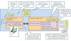
Depending on the functionality of the device that you’re designing, you will still have to incorporate some digital and analog circuitry, and ensure that your radio module works as expected. Figure 1 shows a typical IoT device, in this case with a Wi-Fi module, along with a dc power module and some hardware for the specific IoT device. Several potential issues are highlighted; you will want to be able to easily test and debug these issues.
As you power up your device, the first thing you’ll want to know is if it’s transmitting or not. If a signal is present, you may also want to check that the signal frequency is as expected, that the signal power level and linearity are all correct.
A spectrum analyzer offers the simplest way to test for these characteristics. It will not only indicate whether your signal is present, but it will measure its frequency and power level. You may also need to decode your signals or extract the digital data from the signal. In this case, a vector signal analyzer (VSA) is essential.
Of course, your radio will only transmit what it’s been told to. In other words, the “Customer Application” module from Fig. 1 is the brains of the device—it will be programmed to control all of the modules, including the radio.
If, for example, the radio isn’t transmitting as expected, you will want to know why. Is it down to incorrect control signals being sent to the radio? Is it incorrect bus commands being sent? Are there issues with the voltage supply to the radio?
To debug RF, analog, and digital parts of your design, it’s essential to have an oscilloscope that can capture all of these signals simultaneously, both in the time domain (traditional scope functionality) and frequency domain (traditional spectrum-analyzer functionality).
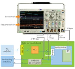
The latest mixed-domain oscilloscopes include a dedicated spectrum-analyzer channel, enabling all of these signals to be captured simultaneously (Fig. 2). Time correlation allows for possible issues to be cross-related. For instance, if your radio isn’t transmitting as expected, it may be that monitoring the control bus commands being sent to the radio while monitoring the RF signal shows not only the problem itself, but also what’s causing the problem.
Receiver Testing
You will also need to test that your IoT radio module’s receiver is able to capture the appropriate RF signals. On top of that, you may need to check that it can filter out undesired RF signals.
The receiver-sensitivity test is a common requirement of all radio receivers, to make sure the device receives and decodes an appropriate signal. In most cases, you need to generate a desired signal at a reasonable power level and then gradually decrease the power to a point where the device can no longer receive and decode the signal. If this measured signal strength is below the “receiver sensitivity” requirement, then the device has passed the test.
The easiest way to generate an RF signal to the appropriate radio standard is to use a vector signal generator (VSG). This instrument is able to generate RF signals that have been modulated (digital information encoded onto the signal), and allows for the creation and transmission of a host of different radio signals
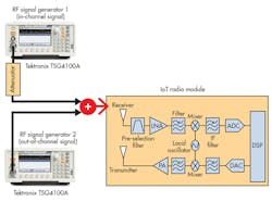
It may also be necessary to check that the receiver can block unwanted RF signals, while at the same time receive and decode a desired signal. This may include signals being generated by another identical device to yours, but transmitting on another channel. The receiver blocking test allows for this to be carried out. As shown in Figure 3, the test requires two VSGs and an RF mixer.
Maximizing Battery Life
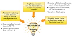
A typical IoT device contains at least one sensor, a processor, and a radio chip that operates in different states and consumes currents from hundreds of nanoamps to hundreds of milliamps in a matter of tens of microseconds. Characterizing low-power-consumption devices to ensure that you stay within a given power budget isn’t a trivial matter. The challenges, summarized in Figure 4, include accurately capturing a wide dynamic range of current, capturing complex and fast transmit-mode current waveforms over time, ensuring stable and accurate power to the device under test, and more.
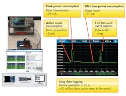
To help make it real, the broad range of current levels that may need to be measured in an IoT device is illustrated in Figure 5. In this example, an energy-harvesting device is being evaluated using a 7½-digit graphical sampling digital multimeter (DMM). The device has built-in temperature and light sensors. It also reports back battery levels as energy is collected through solar cells. When in action, it reports sensor information every second for 30 seconds and then goes into sleep mode. The active transmit/receive events consume the most power, about 29 mA. But when in sleep mode, it only consumes about 70 nA.
Many IoT designers struggle with one common question: What instrument should be used to accurately evaluate the power-consumption characteristics of an IoT device? Is it an ammeter, or will an oscilloscope with a voltage or current probe prove adequate?
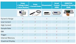
The table below compares the common current-measurement instruments available today, along with the most important functions. As you might imagine, each instrument excels in different areas. Scopes and probes, for example, are well-suited for high currents and fast transients. Picoammeters and typical DMMs are more suited for low-current measurements, but not necessarily for speed. Graphical sampling multimeters are relatively new on the market and offer a more comprehensive set of capabilities compared to traditional instruments.
Wireless Pre-Compliance Testing
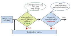
A full-compliance test for an IoT design in a certified lab is expensive—up to $30,000 for the first pass—with costs increasing if more visits are required. Even if you have your own internal full-compliance lab, it takes a significant amount of time to perform compliance testing. Failure of these tests can mean some level of time-consuming redesign and retesting. As Figure 6 illustrates, it’s best to do pre-compliance verification prior to the end of the design cycle as a practical way of reducing risk of failure during compliance testing.
Unlike full-compliance testing, your pre-compliance test procedures needn’t conform to international standards to deliver value and insight. The goal is simply to uncover potential problems and reduce risk of failure at the expensive compliance test stage. The equipment used can be non-compliant and have lower accuracy and dynamic range than compliant receivers—as long as sufficient margin is applied to the test results. Pre-compliance testing typically requires the following equipment:
• Spectrum analyzer with peak detector (quasi-peak optional)
• Preamplifier (optional)
• Antenna with non-metallic stand for radiated emissions
• Line-impedance stabilization network (LISN) for conducted emissions
• Power limiter for conducted emissions
• Near-field probes for diagnostics (optional)
Conducted Emissions Test
Figure 7 shows the pre-compliance setup for conducted-emissions testing. The device under test is a universal ac-dc power adapter for a laptop computer. For conducted measurement, instead of antennas, you use a LISN. It’s essentially a low-pass filter that’s placed between an ac or dc power source and the DUT to create a known impedance, as well as provide an RF noise measurement port. It also isolates the unwanted RF signals from the power source. Adding a preamplifier is a good way to boost the relative DUT signal levels.
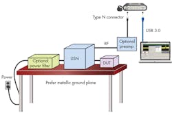
In this example, it’s worth pointing out that the interference being conducted on a 60 -or 50-Hz power supply can also create issues in some cases. While most of the conducted EMI tests specify a measured frequency range of 9 kHz to 1 GHz, it can be useful to measure the signals at lower frequencies when the need arises.
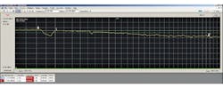
For best conducted EMI measurement results, it’s advisable to use two LISNs: one for a defined impedance to the DUT; and one to go to the spectrum analyzer or receiver. However, one LISN is a must. Given that this was low-cost power supply, the conducted emission unsurprisingly went above the limit at approximately 172 Hz (Fig. 8).
Radiated-Emissions Test
When selecting a test site for radiated-emissions testing, it’s best to pick a location that will minimize external signal sources. Rural areas, conference rooms, or basements are good because they minimize signals that might mask the DUT emission levels you’re trying to measure. Figure 9 shows a block diagram of a typical radiated-emissions test setup.
For these measurements, three very low cost printed-circuit board log periodic antennas and a biconical antenna were used. The antennas were mounted on a tripod for easy placement. The antenna factors (AF) and cable loss should be input into the spectrum analyzer for field-strength correction. A biconical antenna was used for the 20- to 200-MHz frequencies. The longer 20- to 200-MHz wavelengths require a larger antenna; the background noise also may be an issue as it includes many radio broadcast frequencies.
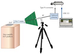
Pre-compliance testing is often done at different distances from the DUT, such as one meter and a few centimeters. Reducing the distance between the DUT and the test antenna increases the ratio of the DUT signal strength to RF background noise. Unfortunately, near-field results don’t translate directly into the far-field tests used in EMI compliance testing, so be careful about drawing conclusions. Adding a preamplifier is another good way to boost relative DUT signal levels.
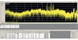
Prior to turning on your DUT, it’s important to evaluate and characterize your test environment. Does enough signal room exist between the limit line and your ambient noise floor? Are there known signals that can be reduced? Do you need to move your test setup to a quieter environment?
Once you are satisfied with your background noise, turn on the power to your DUT. The differences between the two measurements are the emissions from the DUT as shown in Figure 10. In this example, a Wi-Fi demo board that had already been through EMI compliance testing was evaluated, so there were no failures to detect. The good news is that if you set up your testing correctly and nothing comes close to the limit line, it may mean that you’re ready for compliance testing.
Another important aspect of wireless-enabled IoT devices is intentional radiator testing. An intentional radiator is any device that broadcasts radio energy (not infrared or ultrasonic energy) to perform its function. Devices that are intentional radiators are also subject to unintentional testing requirements. Emissions at frequencies other than what the device is designed to use can occur because of internal circuitry.
When evaluating spectrum analyzers for this type of testing, it’s important to select an instrument that can capture at least the third harmonic (if not more) of the radiated signals being generated within the device. The test setup for an intentional radiator is the same as the radiated-emissions setup shown above. However, in this case, the frequencies of interest are limited to the radiated frequencies and frequency masks defined by the specifications, such as Wi-Fi, Bluetooth, etc.
Summary
The Internet of Things is more than just a buzzword. It’s an opportunity to create additional customer value through smart devices and analytics. To some teams building IoT devices, hardware is just the beginning—the foundation upon which you build software and analytics capabilities.
Overcoming the challenges presented here allow you to build that foundation to make your IoT designs more useful and resilient. Putting together an IoT-ready test suite doesn’t need to be expensive or difficult, and will put you on the right track toward a successful outcome.

About the Author
Wilson Lee
Technical Marketing Manager
Wilson has over 25 years of technical marketing, technical sales leadership roles with manufacturers such as CTS Electronic Components, as well technical/value-add distributors such as Richardson RFPD and Premier Farnell. Wilson has focused heavily on design and design engineer engagement within the RF/wireless, industrial power, and industrial automation market segments.
Wilson earned his Bachelor’s of Science at Cornell University. He has lived in New York, Chicago, and Asia through his career, and currently resides in Portland, Oregon.
Comment About the Article
To join the conversation, and become an exclusive member of Electronic Design, create an account today!

Leaders relevant to this article: