What’s All This Absurd Filter Stuff, Anyhow?
Download Volume 3 of the Bob Pease eBook series.
This morning, some darned kid engineer (rather bright for a 15-year-old!) asked me if I could show him anywhere he could add a little narrow-band boost or cut to a circuit for an audio signal, perhaps with a Q of 4 or 5. I told him sure, I could find a cookbook circuit in any number of audio handbooks, such as the recent reprint of the old 1976 NSC Audio-Radio handbook, available at www.AudioXpress.com for about $16.
Then he asked me if he could have this circuit with an adjustable center frequency. I mean, okay, some dynamic equalizers do many things well. But a person might want the center-frequency to be adjustable for a special case.
Oh?
“Cut that out!” I told him. “Nobody has ever seen that or done that as an adjustable-frequency filter! And it’s the most silly-assed question I’ve seen all week!! And it’s absurd and impossible...”
Then I pondered this and told him, “But, on the other hand, I just remembered that I do know how to do it. There’s probably nobody else in the world who knows how to do it, but I can do it. And changing the center frequency doesn’t goof up the gain or the bandwidth.”
Doing the Absurd and Impossible
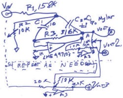
Take that bandpass filter on page 237 of my orange-cover book, Analog Circuits (World Class Designs), the one where trimming the FCenter does not goof up the gain or BW, per the figure. Set up your desired BW. Get it running. The best thing about this bandpass circuit is that the bandwidth depends only on R3 and the C’s: BW = 1/(π × R3C).
The gain depends only on R3/(2 × R1). If R3 = R1 × 2, the gain is 1. No matter what it looks like, R2 is not a trim on gain. It has no effect on gain or BW. R2 is just a trim on the center frequency. The center frequency depends fairly accurately on 1/[√(R2 × R3) × (2πC)]. So, the R2 resistor has sort of a square-root effect on the center frequency. It’s not really linear, but it’s usable. (You could use a logarithmic pot for this if you want to.)
Note that I did say that the BW is not affected by R2. But if the center frequency changes, and the BW does not, then the Q can change somewhat. If you vary the center frequency a bare half octave, up or down, the change in Q may not be too bad. If that’s okay, it’s okay. If not, you might use a multipole double-pole double-throw (DPDT) switch to switch some capacitors out and others in. Be my guest. But it’s worth a try, I think. It depends on what kind of band-pass filter you are trying to make. Does this circuit do the job okay? Do you need absolute precision? Put in matched polys rather than cheap mylar.
Now, take this filter’s output (A) and shove it through a unity-gain inverter (A2) to make (B) = (–A). Run a pot such as 10k from A to B. Send the wiper to a 20k resistor to a summing point of a third amplifier A3. Send a suitable fraction of A through 20 or 18k to the summing point. So now the R2 that goes to ground can tweak the center frequency without goofing up the rest of the filter, maybe over a 2:1 or 3:1 frequency range. And, the new 10k pot can give you boost (+6 dB) or cut (–36 dB or more).
Not bad. I had to save this one to publish as a column. And I first wrote up that basic band-pass filter in 1971, 39 years ago! I still have a good copy of that Philbrick Applications Note, and it had no errors in it. It is still a useful bandpass filter, and it can now help you make a notch filter, which I did not realize at the time.
If you are trying to “add” a little cut (or boost) to some audio circuit frequency response, try it. It might just work well. Are you trying to notch something out? How does it sound? This is such a small, cheap, simple circuit, you could add in two tuned circuits to subtract harmonics for higher resolution.
The values shown are for 50 or 60 Hz. If you want to add a second filter for 120 or 180 Hz, as shown at Fig. C, change the R’s or the C’s and be my guest.
Comments invited! [email protected] —or:R.A. Pease, 682 Miramar AvenueSan Francisco, CA 94112-1232


