Download Volume 3 of the Bob Pease eBook series.
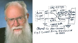
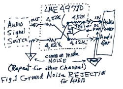
IT’S WELL KNOWN THAT audio power amplifiers like to get a good set of grounds, or noise around the inputs may not be rejected properly, causing hum and buzz. So when a guy called me asking how to clean up his interface from his clean audio signals to his LM3886 power amplifier, whose ground system was pretty noisy and lumpy, I thought for a second and replied that the solution was easy (Fig. 1)!
The set of four 4.02-k resistors (1% R’s but matched to 0.1%) make up an adder-subtractor circuit—straight from Philbrick’s 1955 Applications Manual. Let’s stand at the power ground for our scope ground. If there is a quiet signal “out,” referred to its analog ground “A,” fine. But we must beware of any common-mode (CM) noise, which would appear between the A ground and the PWR ground. This noise might be related to any kind of ambient noise, or noise on the power amplifier’s supplies, or (in a vehicle) automotive transients and radio-frequency interference (RFI). I told this guy, “This circuit will reject any and all such noises.” The old equations give you:
Amplifier VIN – (VPR) = V (signal out) – VA ground
I recommended an LME49710, which has 50 MHz of bandwidth and good clean gain and linearity and noise rejection, per www.national.com/an/AN/AN-1671.pdf. I recommended a “gimmick” of teflon twisted pair as CF, starting at 6 in. and unwinding it as needed. I mean, we don’t know exactly what kind of noises there will be, or how much of the wiring strays. Still, the op amp should be supplied with reasonably quiet power that is tied to the PWR ground. The 4k resistors do not have to be closely matched to ensure gain accuracy—but to help give you good common-mode rejection ratio (CMRR), much better than 1% R’s will do. If you wanted 80 dB, you’d have to trim them.
Opportunity
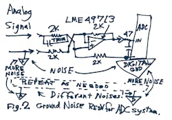
After I hung up, I could not stop thinking of this “problem = ~ opportunity.” Why does this look familiar? I thought about some of the problems my colleague Nick Gray had been trying to solve over the years. Hey! this looks just like the problem with analog signals that need to be sent to an analogto- digital converter (ADC)! You have an analog ground plane and a digital ground plane. But if you try to just strap the grounds together, you’ll get absurd noises.And if you have one ADC, the CM noise rejection can be bad. But if you have one analog ground plane and one big digital ground plane that are serving two or four or more ADCs, the CM noise coupling can be horrible! What’s a mother to do?
The adder-subtractor shown in Figure 2 will reject the CM noises, neatly, using one adder-subtractor per ADC channel. The clean, quiet voltage that is sent in between the signal and VA will re-appear at the adder-subtractor’s output, referred to power ground, for each channel. The old equations give you:
VOUT – (VDIGITAL GND) = V (signal out) – VA ground
Now, the LME49710 mentioned above may have a signal bandwidth of just 20 MHz, plenty for audio or for some ADCs. It may be trimmable to a CMRR of 70 dB out to 2 MHz. That’s what I saw when I actually built it. But what if you need a fast ADC and a lot of CMRR versus frequency?
A Key Modification
Let’s swap in the LME49713, a fast currentfeedback amplifier (CFA), which will pass signals up above 90 MHz, and we may be able to get decent CMRR and noise rejection out past 20 MHz. (The resistors have been cut to 2k to make sure you can get full bandwidth. It might run even a bit faster if you chose 1.2k.)The LMH6714 can go out to even faster, 400 MHz. But the ’49713 may have better linearity. Hard to tell. When you need to do precision work plus fast bandwidth, everything has to be engineered and tested. The circuit might change slightly if you need fast, clean step response rather than just wide bandwidth for sines.
Will that be fast enough for a pretty broad-band ADC? Well, that will depend on the actual circumstances of your system needs. I mean, you could always have more CM noise than this adder/subtractor could quash. I did my testing with 10 V p-p. Could this be used in addition to a Balun? Insert that ahead of the first two 2k resistors. Probably. I mean, when things get fast, then you always have to be prepared to do some real engineering. Still, this is one good tool to add to a good toolbox, when you have to accommodate (and reject) many kinds of nasty noises, conducted and induced from radiated noise.
For this case, adding a few pF of Cf seemed to be doing more harm than good, so I installed several inches of “gimmick” = twisted pair as a capacitive CMRR trim, for the signal path going to the positive input.
What’s the big deal with the “adder-subtractor”? When George Philbrick developed the K2-W, which was one of the first operational amplifiers with differential inputs, it facilitated simple adder-subtractors that did not need a dozen resistors and two or more chopper-stabilized amplifiers and hundreds of watts. George never had access to any 400-MHz op amps as we can easily buy these days. He’d be impressed with modern op amps—and applications circuits.
Can these amplifiers provide a voltage gain other than 1.0? Sure—and you have to engineer it. And to get good results, you always have to plan a good layout. This is just a start, to indicate all the things you can do.


