Why You Need Level Shifting in Buck-Boost Circuits
Members can download this article in PDF format.
What you'll learn:
- Use of buck-boost circuits in switching-regulator ICs.
- Considerations in level-shift circuit design.
- Switching regulators with internal level shifting.
The magnitude of the negative voltage generated by inverting buck-boost circuits can be higher or lower than that of the available positive voltage. For example, –8 V or even –14 V can be generated from +12 V. When working with a switching-regulator IC that has an inverting buck-boost circuit, communications pins may be needed in the system design. If they are required, it’s essential for designers to remember adequate level shifting so that synchronization and enable signals can be utilized.
What to Consider When Designing Level-Shift Circuits
The inverting buck-boost topology is one of the basic switching-regulator topologies, requiring just one inductor, two capacitors, and two MOSFETs as switches. The switches can be driven with any buck regulator or controller. The availability of possible switching-regulator building blocks is therefore large. Figure 1 shows the inverting topology with all of the necessary components.
A buck-boost circuit with an ADP2386 buck regulator is depicted in Figure 2. If a buck-regulator IC is used for the inverting circuit, the ground connection of the IC is at the generated negative voltage. The original output voltage from the buck regulator is connected to the system ground. The buck regulator in the inverting topology references its own ground to the set negative voltage because the output voltage is connected to the system ground. The reference ground for the IC (GND in Figure 2) isn’t connected to the system ground.
As a result, these two grounds aren’t at the same potential. The switching-regulator IC ground becomes the generated negative voltage. All pins on the switching-regulator IC are now referenced to the generated negative voltage, rather than to the system ground. Consequently, the communication lines and connections from the system to the IC and vice versa need level shifting to guarantee safe communication and prevent damage. The relevant signals are typically SYNC, PGOOD, TRACKING, MODE, EN, UVLO, and RESET.
Figure 2 shows a possible level-shift circuit with two bipolar transistors and seven resistors (in blue) for one signal. This circuit requires a certain amount of space and adds complexity to the circuitry as well as costs. Such a level shifter would have to be implemented separately for all signals previously mentioned. It is especially complicated when a switching regulator IC uses a digital bus such as the Power Management Bus (PMBus). Then, the entire bus connection has to be operated with level shifting or galvanic isolation.
Eliminating External Level-Shifting Circuitry
One way to avoid this external circuitry is to use a switching-regulator IC that’s designed specifically for inverting voltages. For example, Analog Devices offers a family of such ICs that are variations of buck-regulator ICs. They’re designed to facilitate communication between the system, i.e., the entire electronic circuitry, and the inverting switching-regulator IC. External level shifting as shown in Figure 2 isn’t needed.
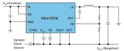
Figure 3 shows the MAX17579 switching-regulator IC, which generates a negative voltage from a positive voltage. As can be seen, the circuit is much more compact than the one in Figure 2.
Simulation tools such as LTspice or the EE-SIM design and evaluation environment can provide a better understanding of the regulation behavior and the potential differences in an inverting topology. Level-shift circuits can be designed and optimized with these tools. ICs like the MAX17579 can also easily be simulated with the EE-SIM design tool.
Read more articles in the TechXchange: Power Supply Design and in the Library Series: Ideas for Design.
About the Author

Frederik Dostal
Power-Management Technical Expert
Frederik Dostal is a power-management expert with more than 20 years of experience in this industry. After his studies of microelectronics at the University of Erlangen, Germany, he joined National Semiconductor in 2001, where he worked as a field applications engineer, gaining a lot of experience in implementing power-management solutions in customer projects. During his time at National, he also spent four years in Phoenix, Arizona (USA), working on switch-mode power supplies as an applications engineer.
In 2009, he joined Analog Devices, where since then he held a variety of positions working for the product line and European technical support, and currently brings in his broad design and application knowledge as a power-management expert. Frederik works in the ADI office in Munich, Germany.
Also check out my:
William G. Wong
Senior Content Director - Electronic Design and Microwaves & RF
I am Editor of Electronic Design focusing on embedded, software, and systems. As Senior Content Director, I also manage Microwaves & RF and I work with a great team of editors to provide engineers, programmers, developers and technical managers with interesting and useful articles and videos on a regular basis. Check out our free newsletters to see the latest content.
You can send press releases for new products for possible coverage on the website. I am also interested in receiving contributed articles for publishing on our website. Use our template and send to me along with a signed release form.
Check out my blog, AltEmbedded on Electronic Design, as well as his latest articles on this site that are listed below.
You can visit my social media via these links:
- AltEmbedded on Electronic Design
- Bill Wong on Facebook
- @AltEmbedded on Twitter
- Bill Wong on LinkedIn
I earned a Bachelor of Electrical Engineering at the Georgia Institute of Technology and a Masters in Computer Science from Rutgers University. I still do a bit of programming using everything from C and C++ to Rust and Ada/SPARK. I do a bit of PHP programming for Drupal websites. I have posted a few Drupal modules.
I still get a hand on software and electronic hardware. Some of this can be found on our Kit Close-Up video series. You can also see me on many of our TechXchange Talk videos. I am interested in a range of projects from robotics to artificial intelligence.


