Comparing Single-Phase Controller and Multiphase Converter Solutions
What you’ll learn:
- The difference between a controller and converter design.
- Why you want to use a controller versus a converter design.
It’s become trendy to multiphase or stack devices as power requirements across applications continue to push controller solutions to limits that require a large bill of materials (BOM), larger solution sizes, and thermally challenging designs. Now that new converters can stack or multiphase their outputs to achieve higher output currents, the question becomes: “What’s the best solution—a single-phase controller or a paralleled two-phase converter?”
Here, we’ll compare a single-phase Texas Instruments (TI) LM5148-Q1 controller design to two TI LM70880-Q1 converters interleaved in a dual-phase design. These devices are good options for emerging 24- and 48-V end equipment in the automotive, enterprise, and industrial sectors, including hybrid electric vehicles (HEVs), onboard chargers, robots, and data-center servers. These applications require large input-voltage (VIN)-rated devices to handle transients as high as 65 or 80 V.
Key Design Considerations and Tradeoffs for Power Solutions
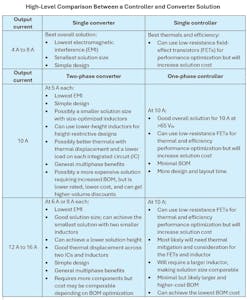
For 48-V designs, a controller solution such as the LM5148-Q1 was the only option for power-stage designers. However, with the LM70880-Q1 converter, you now have more options for solutions at output currents from 4 A up to 16 A. The table lists the general high-level tradeoffs and benefits of the two solutions across output currents.
It’s crucial to remember that overall thermal constraints and application-specific requirements drive solution decisions. At higher output currents and high ambient temperature conditions, thermal challenges remain a consideration for most designs.
Maximizing Efficiency and Managing Thermals in Power Designs
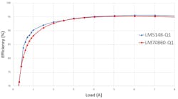
Overall, a controller solution is still best when efficiency and thermals are a major aspect of a design. And while it’s possible to use low-resistance FETs yielding low conduction losses, you must weigh the tradeoff of the cost difference between good and better performance components. Improvements in IC design and packaging have enabled converters to reach good and comparable thermal performance and efficiency in an integrated solution (Figs. 1 and 2).
While calculators and simulations provide a good start for estimating whether a solution could work for a design, factors affecting thermal performance include layout, component selection, printed circuit board (PCB) size, PCB layers, PCB layer composition, airflow, and ambient temperature.
A controller may offer more options to lower thermals, but using multiphased converters also enables each device to operate at half the load and thus displace thermals across two ICs vs. one set of FETs. Furthermore, dual-phase converter designs may have to include a co-heating element, depending on layout and PCB design.
Choosing the Right Inductors for Single-Phase and Multiphase Designs
With the converter solution, the current load is shared between devices, enabling you to use lower-rated inductors per phase. These inductors can have a smaller total footprint and be lower in height compared to an inductor in a single-phase solution.
As an example, for an application with specifications of 48 VIN, 5 VOUT, and 400 kHz, a single-phase 12-A design could use a 3.3-µH inductor with an 18.1-A saturation current rating, a footprint of 113 mm2, and a height of 6 mm. A two-phase design at 6-A each could use a 3.3-µH inductor with a 10-A saturation current rating, a footprint of 43 mm2, a height of 6 mm, and the option to use 3.1-mm-tall inductors.
Likewise, for a 16-A design, the single-phase design could use an inductor with a footprint of 246 mm2 and a height of 8 mm, whereas a two-phase design at 8-A each could use an inductor with a footprint of 54 mm2 and a height of 7 mm.
Comparing Solution Sizes: Single-Phase vs. Multiphase Power Designs
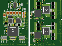
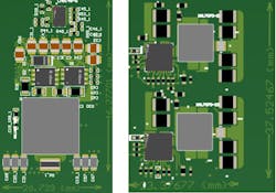
Metal-oxide semiconductor field-effect transistors (MOSFETs) can occupy more than 20% of the total controller solution size, and as we mentioned, the size of an inductor increases with output current because inductor size correlates with its rated saturation current specifications. With these factors, a two-phase converter design with integrated FETs and smaller inductors can still be comparable in solution size compared to a single-phase controller.
Figures 3 and 4 illustrate a mock layout comparison of a single-phase controller design versus a dual-phase design at 12 A and 16 A, respectively. These solution sizes are highly dependent on layout and component selection, where you must trade size and performance for cost and availability.
Multiphase Power Designs: Benefits and Performance Advantages
Multiphase designs benefit from being able to displace loads across multiple devices, and inherently may have better performance in some design and BOM aspects. As outlined in the TI application report, “Multiphase Buck Design from Start to Finish (Part 1),” a multiphase regulator design maintains multiple advantages over a single-phase design. These include decreased root-mean-square input current, reduced input capacitance required, decreased output ripple current, reduced output capacitance required, and improved overshoot and undershoot performance during load transients.
Conclusion: Selecting the Optimal Power Solution for Your Application
The comparisons and data shown in this article outline the value propositions of a solution using typical controller-based designs or new stackable converters such as the TI LM70880-Q1, LMQ644A2-Q1 and TPSM64406. Converter solutions are nothing new for power designers; however, they might be when it comes to emerging 24- or 48-V-based systems.
New 65- and 80-V converters illustrate the integration that’s on the forefront of packaging, FET technology, IC design, and manufacturing. These converters give you an option that enables smaller footprints, lower EMI, and easier-to-design solutions that are scalable to output currents only controllers could achieve in past power designs.
