This file type includes high-resolution graphics and schematics when applicable.
Modern telecommunications applications like 4G Long Term Evolution (LTE) systems as well as forthcoming 5G systems use multicarrier modulation like orthogonal frequency-division multiplexing (OFDM) with quadrature amplitude modulation (QAM). To meet user demands for ever-higher data rates, the system must have wide bandwidth and be able to process both high- and low-amplitude signals.
Since most signal processing is digital, incoming signals must be converted to digital at some point. One solution would be a wide-bandwidth analog-to-digital converter (ADC) with high dynamic range and a sampling rate in the gigabit range. Such an ADC is now available.
Receiver Architectures
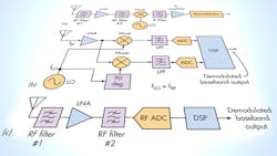
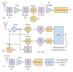
Three basic forms of receiver architectures are used in telecommunications and other software-defined-radio (SDR) applications: superheterodyne, direct conversion, and RF sampling (see figure). The superhet form (see figure, a) is traditional and still widely used. It takes the incoming RF signal and downconverts it with a mixer to a lower intermediate frequency (IF). The signal modulation and bandwidth are retained, but the sampling-rate requirements are much lower.
The superhet has some downsides, though. First, it requires many circuits and filters, which bumps up the cost. Also, the local oscillator (LO), usually a PLL synthesizer, adds phase noise and jitter. On top of that, the mixing process makes the receiver subject to images depending on the frequency bands being used. A dual-conversion architecture with a second mixer and LO solves this problem, but adds more cost and complexity.
A simpler arrangement is the direct-conversion receiver (see figure, b). The LO frequency is equal to the incoming signal frequency, resulting in a difference IF of zero. Called a zero IF receiver, this architecture downconverts the RF signal directly to baseband. Fewer circuits and filters are needed, lowering cost and complexity. The relaxed ADC sampling rates are beneficial, and the image problem of the superhet is eliminated. On the other hand, direct-conversion receivers suffer from a dc offset problem and LO leakage to the input.
An ideal receiver architecture employs direct RF sampling, where the incoming signal is sent straight to the ADC for conversion. This hasn’t been possible until recently, as ADC sampling rates have increased to accommodate the higher RF frequencies including microwave spectrum. In the basic arrangement (see figure, c), some front-end filtering narrows the coverage to the bands of interest. The ADC converts the entire input to a digital bit stream that’s subsequently processed by DSP methods. Direct RF sampling greatly simplifies the design and minimizes cost and complexity. However, it requires fast DSPs or FPGAs to keep up with the digitizing rate. Fortunately, fast ADCs and processing chips are now available to implement this type of receiver.
ADC Considerations
The key specification for sampling ADCs is that the sampling rate must be at least twice the bandwidth of the signal being digitized. That’s right, twice the bandwidth or more. More is better as oversampling, as it’s called, helps retain the fine detail of the signals being digitized. Oversampling also reduces the quantization noise, thereby improving the signal-to-noise ratio (SNR).
For example, assume that you need to digitize a group of LTE carriers, each typically 20 MHz wide. The most common scenario is a group of multiple 20-MHz carriers. Sometimes large spaces exist between groups of carriers.
Consider four groups of ten 20-MHz carriers each spaced from one another by 65 MHz. That’s 800 MHz of carriers, and 3 × 65 = 195 MHz of spacing for a total bandwidth of 995 MHz. Round that up to 1 GHz of bandwidth—and that bandwidth is probably centered around some assigned cellular spectrum frequency in the 2-GHz range. You will need an ADC with a minimum sample rate of 2 Gb/s. However, 3 or 4 Gb/s would be better.
One key point to consider: The ADC is going to convert everything within the input bandwidth. Only one ADC is needed, and it doesn’t care if there are gaps in the digitized spectrum. The big problem now isn’t the sampling rate, but how fast the processing can be done. It will take lots of DSP filtering to sort out the individual 20-MHz channels, as well as perform demodulation and other functions. That calls for fast FPGAs or DSPs and a high-speed interface from ADC to FPGA or DSP.
One solution to the processing-speed problem is to take the ADC output and subject it to the process of decimation. Decimation is the process of removing samples from the ADC output at regular intervals, thereby decreasing the sample rate to a range that can be managed by the processing circuits. Decimation is usually carried out by a FIR filter and an anti-aliasing circuit. The sampling rate can also be reduced via digital downconversion with a digital mixer, numerical-controlled oscillator (NCO), and DSP low-pass filter.
Example of a Fast ADC
Texas Instruments’ ADC32RF45 is an ADC that can implement direct RF sampling receivers. It offers the wide bandwidth and high dynamic range needed for challenging wireless applications. The ADC32RF45, a dual-channel, 14-bit, 3-Gsample/s ADC, maintains an analog input bandwidth of 3.2 GHz. Some typical specifications include a spurious free dynamic range (SFDR) of 69 dB, a SNR of 62.7 dB, and a noise floor of –155 dBFS/Hz.
One important feature is the inclusion of digital downconverters with up to three separate NCOs following each ADC channel. The interface is the JESD204B commonly used to connect with DSPs, FPGAs, and ASICs. There are four lanes per ADC with speeds up to 12.5 Gb/s.
Besides its use in direct RF conversion receivers for cellular, the ADC32RF45 will find applications in MIMO arrays, beamforming, phased-array radar, electronic-warfare equipment, microwave backhaul, cable and wireless broadband, test instruments, and other SDR designs. TI offers the ADC32RF80EVM evaluation module to get you up to speed quickly in designing.
TI offers a series of instructional videos that further elaborate on the ADC32RF45 and its capabilities and uses:
ADC32RF45: 1-GHz Bandwidth RF Sampling Solution
About the Author

Lou Frenzel
Technical Contributing Editor
Lou Frenzel is a Contributing Technology Editor for Electronic Design Magazine where he writes articles and the blog Communique and other online material on the wireless, networking, and communications sectors. Lou interviews executives and engineers, attends conferences, and researches multiple areas. Lou has been writing in some capacity for ED since 2000.
Lou has 25+ years experience in the electronics industry as an engineer and manager. He has held VP level positions with Heathkit, McGraw Hill, and has 9 years of college teaching experience. Lou holds a bachelor’s degree from the University of Houston and a master’s degree from the University of Maryland. He is author of 28 books on computer and electronic subjects and lives in Bulverde, TX with his wife Joan. His website is www.loufrenzel.com.


