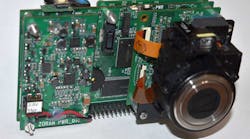
I met with Ricardo Salaverry before the 2019 Analog Aficionados party in Silicon Valley (Fig. 1). Ricardo worked at Zoran Corporation a decade ago, and designed one of the most popular small pocket cameras. I had met Salaverry through engineer extraordinaire Alan Martin. Alan told me Ricardo was the best engineer he had ever met. Since Alan had been a field application engineer at Linear Tech and a factory application engineer at Texas Instruments, he had met a lot of engineers. Saying Ricardo was the best of them was quite the complement.
1. Ricardo Salaverry learned electronics at an early age in Chile. A ham radio enthusiast and consumer product system designer, he was once director of engineering at the ELO Touch division of Tyco.
Using the Vendor’s Help
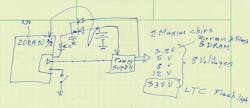
One thing I found interesting was Salaverry’s approach to power design. He had heard stories of a Kodak digital camera exploding in use, and wanted the expertise to ensure that would never happen with his design. “I knew I was not an expert on portable power, so I called Maxim and Linear Tech [now part of Analog Devices].” He used a Linear Tech chip to charge the camera flash. Two Maxim chips made the many system voltages needed to power the sensor, the processor, and the flash memory. Salaverry recalled there were 11 system voltages he needed to make from two AA battery cells (Fig. 2).
2. Salaverry sketched out the power system in the Zoran box camera prototype he designed over 10 years ago.
There was a small section of the Zoran chip that was always on, powered by wired-OR diodes from the battery stack and the power-supply chips. That always-on section was where the on-off switch went. It was imperative that the power switch be a soft switch, controlled by the Zoran chip. If you take a picture and immediately turn off the camera, the Zoran chip had to keep everything running while it read the CCD sensor, did the signal processing and compression, and then wrote to the flash memory. Only then could the power rails turn off.
Sticky Situation
Salaverry ran into a tricky situation familiar to those who design battery-operated products. AA battery cells have an internal resistance. This resistance changes with temperature, as well as the current the battery is delivering. A new alkaline cell will have a voltage of 1.5 V. It’s completely discharged when it reaches 0.9 V. The problem in portable products is that the always-on part of your chip might measure 1 V, until you turn on the main power bus. Then the battery cell will sag down to less than 0.8 V. This would be a major problem if there was not enough charge left to take and store a picture.
Salaverry used a hold-up capacitor at the “OR” node of the diodes. This way, if the user pressed the power button when the battery voltage was barely adequate, the always-on section of the chip had adequate power as the battery voltage sagged below the 1.8-V minimum threshold for two AA cells. This allowed the always-on section to keep working though the sag, and then do an orderly shutdown since there was not enough charge left to take a picture.
A Huge Success
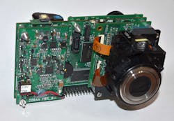
The camera Salaverry designed became a smash hit, in part because of his architecture and in part due to the clever marketing by Zoran. Salaverry’s reference design was not a form-fit-and-function prototype (Fig. 3). Instead, he used high-density connectors with standardized pin assignments so that the Zoran customers could use 1Mpx, 2Mpx, 3Mpx, or 6Mpx sensors. Salaverry made a camera system reference design that let the customer decide what features to include. He did a total of 16 power-supply designs, eight sensor boards, two different Zoran chip boards, along with yearly updates, and two display boards, in the years before the displays were available as a module. The final reference design had a main board with the Zoran chip, a power-supply printed circuit board (PCB), a flash PCB (bulb, not memory,) a display board, and a sensor PCB.
3. The “copy-ready” reference design made by Salaverry allowed Zoran customers to architect their own version of the camera, all so Zoran could sell them the main chip.
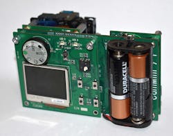
All of these subsystems could be mixed and matched by customers, since Salaverry made sure he had enough pins on his high-density connectors to provide for all of the variations. The marketing people branded the product a “copy-ready” reference design (Fig. 4). The customer would set up his product based on the market or intuition. Then Salaverry would supply his Cadence OrCAD schematics. Afterward, the customer would remove the large high-density connectors and either integrate subsystems on one PCB or use smaller connectors for just the signals that they needed for this specific configuration.
4. The prototype was built up from interchangeable PCBs that could provide different and enhanced functions. The customer would take Salaverry’s schematics and layouts and make their version form-fit-and-function.
Test at Your Behest
Salaverry did something else every design engineer appreciates. He included a connector that brought out many different test signals, and provided plenty of test points on all the PCBs. One secret was judicious use of simulations. Salaverry agrees with Bob Pease, that simulation can lead you astray.
“Bob Pease is right,” he exclaimed to me when I questioned his use of simulation. “But you have to know what you can simulate.” He noted simulating RC time constants, passive networks, and such is simple physics and is sure to be right, if you understand all of the strays and leakages paths. The other secret is to know the quality and range of the simulation models you are using. The proof is in his success. Of 139 circuit boards, 137 of them worked on the first spin. This puts you in the great position of making changes to implement features or improvements—not to get the dang thing working.
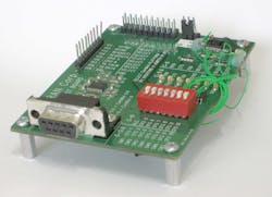
Salaverry also designed a breakout board to help in the camera’s development (Fig. 5). He notes, “The Jig board has a 20-pin connector. This connects to the Cammini 20-pin connector in the front bottom part of the Cammini camera. The connection was made through a ribbon cable. The Jig board has LEDs, test points, and a DIP switch that connects directly to the Zoran chip to change the mode of operation or boot-up mode of the chip. It was a very powerful little board. This little board was all that was needed to fully develop a camera.”
5. Salaverry also designed a breakout board that helped in camera development.
Make Way for the Motherboard
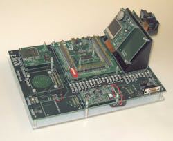
While the modular nature of the copy-ready reference design delighted customers, Salaverry later designed a motherboard that designers could use to test the various boards and subsystems of the camera (Fig. 6). He notes, “The name we gave to the cameras was ‘Cammini’ and the board name was ‘Cammini Extension.’ The Cammini Extension had lots of capabilities for testing, debugging and also for tuning the image sensor.” Allowing an organized accessible way to power and test the various boards was just as important as the reference design itself.
6. To aid in the box camera design, Salaverry created a motherboard of sorts, that allowed for easy testing and development of the various system boards. This was used for his own development as well as given to customers for their development.
The Cammini extension board had the space so that Salaverry could bring out the RS-232 port from the Zoran IC by using a Maxim charge-pump RS-232 chip. This allowed customer’s engineers to plug the reference design into a PC for programming and debugging. The RS-232 interface chip was not needed on the final product, but the customer's engineers loved that it was so easy to interface with the reference design. I asked if there was a JTAG interface, and Salaverry replied, “Nobody needed anything that complicated to set the registers and play with the chip.”
He noted that his design meant the customer did not have to sift through the hundreds of pages of Zoran datasheets to design a camera. The camera design was done, Salaverry had plowed through the Zoran datasheet and all of the others, and made a system that customers could tailor to their own desires—and get to the market fast.
The Wrong Way to Prototype
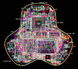
Contrast Salaverry’s prototyping system to my experience at OQO, a palmtop computer startup. We made our first prototype very small and snazzy (Fig. 7). The company was started by an ex-Apple industrial designer, so it was important to him to have something small and sexy to show off to customers, who we figured would be tier-1 computer makers like Dell, HP, and Lenovo. The design effort was hampered by not having a true breadboard design with the major subsystems spread out and available for testing. Maybe that’s why Wired gave us their “Vaporware” award. Twice.
7. The 12-layer PCB for the OQO palmtop computer prototype was too small and crowded to allow for troubleshooting and development.
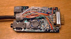
Compounding the error of making the very first prototype form-fit-and-function, I accepted that my part of the project, the wall wart, would also be prototyped at end-size (Fig. 8). It was a challenging design to begin with—the Li-ion charger was in the wall wart, not the product itself. It made for less stuff in the product.
8. The “wall wart” prototype I designed for the OQO computer was also form-fit-and-function—a huge mistake early in development. Note 36-gauge wires soldered to the PCB, along with three VGA coax cables. Worst yet, the Li-ion charger was in this accessory, not the computer itself.
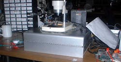
But I accepted the evil mantra “It’s just a prototype,” so I went with the 36-gauge wires and tiny coax cables soldered to the board with no connectors. I had to troubleshoot the design with a microscope (Fig. 9). That I labeled the picture “Alter of human suffering” tells you about not having a spread-out prototype with plenty of test points and access to the all the circuit nodes.
9. Troubleshooting the OQO prototype design was a nightmare, requiring a microscope, a surgeon's coordination, and the patience of Job.
A Good Problem to Have
Zoran’s “copy-ready” concept saw the digital camera chip portion of Zoran’s business go from 1% to 55% in three years. In one year, Zoran supplied 35 million camera chips, into a total market of 103 million digital cameras. They nearly ran the TSMC silicon foundry out of capacity for a while. These are the kinds of problems any company would welcome.
Salaverry told me that the economies were that there was 40 dollars in parts, another 40 dollars in labor and overhead, and the camera was an easy sale at 100 dollars. This meant a manufacturer could spend 80 million dollars and end up with 20 million dollars in profit, easily achieved in nine months or less. No wonder the customers loved his design. We should all be so lucky, and so smart.
