Piezo-Based Approach Dramatically Shrinks VLF Antennas
While everyone is focused on RF signals in the gigahertz-plus range, it’s important to remember that the other end of the electromagnetic spectrum also has its uses. However, signals in very-low-frequency (VLF) RF band present a technical dilemma: On one hand, you can’t easily live with them; on the other, you can’t live without them for some applications cases.
The former assessment is due to their need for extremely large antennas (on the order of kilometers). The latter assessment is a result of their propagation characteristics, including Earth-hugging signals and low atmospheric attenuation, as well as their ability to penetrate seawater with modest attenuation of just several dB/meter (depending on salinity and other factors).1
The VLF band is formally defined as the 3- to 30-kHz slice of the RF spectrum—corresponding to wavelengths from 100 km to 10 km, respectively. And it’s a general guideline that a transmitting antenna should be at least one-tenth the length of the wavelength for reasonable efficiency and suitable radiation resistance, so the VLF-antenna problem is obvious. Still, their propagation characteristic makes them the only option for some specialty communication links such as to submerged submarines.
Now, a consortium of researchers at SLAC National Accelerator Laboratory, SRI International, and Gooch and Housego have simulated, developed, and tested a radically new approach to a viable VLF antenna. These antennas can resonate in a very small footprint while exhibiting low losses. To achieve this, they created an ultra-low-loss, piezoelectric electric dipole driven at acoustic resonance. Therefore, it radiates with efficiency that’s at least 300X higher than previous devices at a comparable electrical size.
Traditionally, a disadvantage of passive high-Q antennas is their low bandwidth. When you’re in the VLF range, effective bandwidths are narrow and thus data rate is also low—on the order of about 100 bits/s.
By using piezoelectricity as the radiating element, the research team was able to dynamically shift the transmitter resonant frequency. They claim that their strain-based piezoelectric approach overcomes many of the fundamental limitations of conventional electrically small antennas (ESAs) and can resonate in a very small footprint while exhibiting low losses, while the high total Q (low loss) no longer constrains the system bandwidth.
They also say they have achieved an exceptionally high system Q with no external impedance-matching network and an effective fractional bandwidth which is 83X beyond the conventional passive Bode-Fano limit.2,3 Consequently, there’s an increase in the transmitter bit rate while losses are still minimized. Furthermore, although they demonstrated this at VLF, the concept directly scales to other frequency bands.
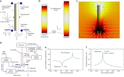
1. How a piezoelectric resonator can be used as a transmitter: Schematic of the lithium niobate rod mounting and excitation mechanisms (a). Mechanical displacement magnitude (in color, magnitude exaggerated for clarity) and the induced electric displacement vectors (arrows) (b). Electric potential magnitude in color along with electric field vectors (c). Electrical schematic of input and output measurements (d). Simulated input-impedance magnitude versus frequency (e). Representative simulations of velocity and electric-dipole moments versus frequency (f). (Source: SLAC National Accelerator Laboratory)
Figure 1 shows the electric dipole moment and external electric fields of this vibration mode, as well as the test arrangement. In addition to extensive simulation, they built a 9.6-cm-long transmitter prototype that’s much smaller than the wavelength of the signal it generates, yet more efficient than a small metal antenna (Fig. 2). They used lithium niobate as the piezoelectric material due to its high electromechanical-coupling ratio.
2. The 9.6-cm-long transmitter prototype underwent field tests. It’s much smaller than the wavelength of the signal it generates, yet far more efficient in the VLF band than a similarly sized metal antenna. (Source: Physics Today)
The VLF RF input signal applied at one end causes the material to expand and contract as the lithium and niobium ions in the crystal’s unit cell shift. This, in turn, polarizes the material. At the antenna’s resonant frequency, a high voltage develops between the antenna’s ends, and the alternating input energy generates a time-varying electric field, causing the antenna to radiate as an electric dipole.
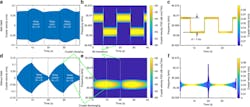
Figure 3 shows the measured effect of using direct antenna modulation (DAM) to modulate a resonator with Q >300,000 with a frequency separation of 7 Hz and a frequency-shift-keying (FSK) rate of 0.05 Hz.
3. Shown is the measured effect of direct antenna modulation (DAM) to modulate a resonator (Q >300,000) with a frequency separation of 7 Hz and an FSK rate of 0.05 Hz with (DAM) (a through c) and without DAM (d through f). Note that images a and d are time-domain measurements, images b and e are time-frequency spectrograms, and images c and f are Hilbert transforms. Also note that one of the resonant frequencies is intentionally detuned to minimize the effect of different Q on the amplitude of the output signal. (Source: SLAC National Accelerator Laboratory)
Full details of their project, including the theory of the concept, simulation results, and field data are in their paper “A high Q piezoelectric resonator as a portable VLF transmitter” published in Nature Communications. A brief and less-technical overview can be found in Physics Today, “A strain-based antenna paves the way to portable long-range transmitters.”
References
1. Radio Science Journal of Research/NIST, “VLF and LF Fields Propagating Near and Into a Rough Sea,” (1965)
2. University of California Santa Barbara, “Impedance Matching” (page 5)
3. Marquette University, “Impedance Matching” (slide 25)


