Download the "What's All This Algebraic Equation Stuff, Anyhow?" eBook.
Article updated 10/04/22
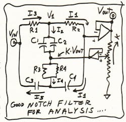
As I said in the last issue, I wanted to derive the equations for a network of Rs and Cs—which just happens to be an analog filter (see the figure). Let's just look at the principle here. We will assume that there's an output voltage VOUT, and that there's a current I1. What is V1? V1 = VOUT + I1 × R. If we know VOUT and k × VOUT, then there's a current I2 = [VOUT + I1 × R − k(VOUT)] × 1/(2pC).
Now, we know that I3 = I1 + I2, so VIN must be a nice linear function of VOUT and I1, namely:
VIN = F1 [VOUT + F2(I1)]
where F1 and F2 are functions of R1, R2, C1, and C2—and of frequency. We derived that equation just by studying the currents through R1 and R2, and C1 and C2.
Similarly, we can derive that VIN also is a linear function of VOUT and I1, and of R3, R4, C3, and C4—and of frequency:
VIN = F3(VOUT) + F4(I1)
where F3 and F4 are functions of R3, R4, C3, and C4.
Now, let's try turning around that second equation for VIN, so it reads in terms of I1:
I1 = (1/F4) × [VIN − F3(VOUT)]
If we simply substitute that expression for I1 into the first equation, we have a messy (but conceptually simple) equation that's only in terms of VIN and VOUT:
VIN = F1 [VOUT + F2(I1)]
= F1 {VOUT + (F2/F4) × [VIN − F3(VOUT)]}
You only have to rearrange all of these terms to get the ratio of VIN to VOUT. The result comes out as I showed it a couple of weeks ago.
Gain = [1 + (pRC)2] / [1 + 4(1−k)pRC + (pRC)2]
Of course, manipulating all the terms of all the equations isn't too simple. And you really want to avoid making sloppy errors, or you will get very discouraged. It's very helpful to know what the answer is supposed to look like so you will know when to stop. Additionally, it's good to have several large pieces of paper, 11 by 17 in. or similar, to simplify what you carry along and write down.
Comments on the actual filter: If you set k = 0 and just connect the bottom of the RC network to ground, you get a nice simple filter. But the Q is lousy, about 1/3. Thus, if you wanted to notch out some 120-Hz noise, you would also badly attenuate any signals at 50 or 100 Hz, and at 150 or 250 Hz. In many cases, that would be unacceptable.
So by merely adding the op amp, you can get k up to 99%, which gives you a Q of about 9. Therefore, frequencies below 100 Hz or above 140 Hz will get less than 1 dB of attenuation. Note that if k is very close to 1, it isn't important to have the second follower. You probably won't even need it, as the impedance of the output attenuator will be quite low. That makes a pretty good notch filter, and it's simple.
Next time, I will walk you through the derivation for the response for the simplest kind of RC filter, a basic Sallen-Key low-pass filter. Then if you ever have to do it yourself, you will know that it's not so hard.
I can't say that the equations above are really easy, but I think I've indicated how, by approaching it the correct way, you can get there. The same is true for other filters.
All for now.
This article was published in Electronic Design Oct 15-5, 2001
see Bob Pease Remembered — One Year Later
This is how Bob always ended his blog. The information is no longer valid.
/ Comments invited!
RAP / Robert A. Pease / Engineer
[email protected]—or:
Mail Stop D2597A
National Semiconductor
P.O. Box 58090
Santa Clara, CA 95052-8090
P.S. Before putting this story to bed, I decided to be a real sport and build this notch filter again, and it worked exactly as I claimed. /rap


