MIMO, Beamforming Methods Enhance Auto Radar Angular Resolution
Download this article in PDF format.
Who would have thought that something as complex as radar would turn out to be one of the best sensing methods for implementing vehicle safety features like advanced driver-assistance systems (ADAS)? Such systems now rely on multiple sensors to detect surrounding objects. These include video cameras, ultrasonics, radar, and LiDAR. However, recent developments indicate that radar may be most versatile sensors for automotive applications.
Sponsored Resources:
- Imaging radar - one sensor to rule them all
- Automotive Imaging Radar System - Long Range Detection
- Imaging radar using cascaded mmWave sensors
Sensor Sensibility
A variety of sensors are used for proximity detection; that is, sensing the direction and distance and even speed between objects. Such sensing is at the heart of ADAS and autonomous driving systems. Currently used sensors come with benefits and limitations. For example:
Video cameras: Cameras offer very high resolution and color detection. They have significant object recognition and differentiation capability. Their limitations include the inability to see in the dark or through fog, smoke, rain, and snow. They can be blinded by glare.
Ultrasonic detectors: These sensors work like radar in that they send out a signal and detect its reflection. Ultrasonic frequencies used range from 40 to 100 kHz. They’re effective for sensing objects close by, and even transparent surfaces like glass that may be missed by cameras. Such detectors are inexpensive, but they lack the necessary range and speed of response required for ADAS.
LiDAR: Light detection and ranging sensors offer a full 360-degree view of their surroundings. An infrared laser scans the surrounding area, captures the scene, and produces a 3D image of close objects. LiDAR is an excellent sensor, but it’s very expensive. That rules it out as a sensor for most vehicles. No doubt, prices will eventually come down as improvements and volume increase.
Radar: Radar’s benefits are long-range object detection combined with accurate distance and speed estimates of surround objects. Its angular resolution isn’t as good as a camera, but improvements are addressing that limitation. New millimeter-wave (mmWave) chips are coming down in price and being widely incorporated in new ADAS. Also, novel approaches are emerging to address the resolution problem.
Currently, most automotive ADAS use both radar and a camera. The radar detects objects over a longer range than a camera. Yet the camera is used to validate the radar’s outcome before there’s any reaction. However, recent developments may just make the radar alone more desirable.
Imaging Radar Improves Resolution
Imaging radar is essentially the technique of using multiple radar transmitters (TX) and receivers (RX). Multiple radar signals are captured and processed in a unique way that creates the resolution needed for successful automotive applications. This outcome is achieved by adopting some of the advanced wireless techniques like multiple-input multiple output (MIMO) and beamforming.
But first let’s talk about the radar itself. IC radars have been available for a while now. Their price has decreased, and they have been almost universally adopted by automotive manufacturers for their ADAS systems. These radar chips, operating in the 76- to 81-GHz range, use a form of radar called frequency-modulated continuous wave (FMCW). It transmits a signal called a chirp—a short burst of RF energy of increasing frequency. The chirp is reflected from the nearby object and picked up by the receiver. Combining the transmitted and received chirps makes it possible to calculate the range between chips. The speed of the remote object and the angle of signal’s arrival can also be determined. All of this is available in one IC.
The main problem we’re dealing with here is the radar’s inability to distinguish between two objects that are within the same range and velocity. One example is resolving a parked car and an adjacent car that’s stopped or slowly moving. Or being able to differentiate a tunnel entrance from a stopped truck just inside the tunnel. This ability is a function of the angular or spatial resolution. Angular resolution must be acceptable in both azimuth and elevation directions.
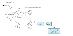
1. Shown is radar configuration with one TX and one RX antennas.
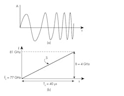
Figure 1 shows a simplified radar configuration. A frequency synthesizer generates the chirp that can be illustrated as a frequency modulated wave (Fig. 2a). The chirp increases linearly in frequency from 76 GHz to 81GHz over a 40 µs period (Fig. 2b). A sequence of chirps is generated, amplified in the transmitter (TX), and sent to the antenna. The signal is then reflected from the distant object and returns to the radar receiver (RX). The return signal is delayed in time during its travel to the object and back. Subsequently, the return signal is combined with the synthesizer output in a mixer that produces an intermediate frequency (IF) or tone. Afterward, the mixer output is filtered and digitized in an ADC and sent to a processor where computations regarding distance, speed, and angle are made.
2. The radar chirp signal is illustrated in two ways: Linearly increasing frequency in the time domain (a), or frequency varying linearly over time (b).
To improve angular resolution, multiple receiver (RX) and/or transmitter (TX) antennas must be used. The concept is illustrated by describing a single-input multiple-output (SIMO) radar. It uses one TX and two RX antennas (Fig. 3). The transmitted signal is reflected and returns at an angle θ.
3. The fundamental technique of resolution improvement uses one transmitter and two receivers.
The signal arrives at antenna 2 somewhat later than at antenna 1 because of the distance between the two antennas (D). This time delay results in a phase difference that can be interpreted to be the angle of arrival. With D = λ/2, the field of view is ±90 degrees. This phase difference produced by different antenna spacings translates into improved resolution. The phase angle is then sampled across the antennas in sequence, and subsequently subjected to a fast Fourier transform (FFT).
Even better resolution can be achieved with four or even eight receive antennas. Four antennas narrow the resolution down to about 30 degrees. Eight antennas will deliver 15 degrees resolution. The problem with this is that each receive path includes the analog-to-digital converter (ADC) and processing. Each return signal creates a different IF “tone.” By processing these signals sequentially with an FFT, the tones can be separated and identified.
Systems with eight receive antennas are complex and expensive. The solution is to adopt a MIMO configuration. This consists of two transmitters and four receivers. Making the same four receive antennas work with two transmitters requires that the receivers be capable of separating the signals from two transmit antennas. This can be accomplished with either a time-division-multiplexing (TDM) arrangement or binary phase modulation (BPM). Then concatenating or cascading the multiple radars operating synchronously results in a high degree of angular resolution.
Reference Design: Imaging Radar Using Cascaded mmWave Sensors
Creating a MIMO radar system is a challenge for even the most experienced engineer. Now, Texas Instruments has developed a reference design that speeds up and simplifies the development of a high-resolution imaging radar.
This reference design is a cascaded imaging radar radio-frequency (RF) system. Cascaded radar devices can support long-range-radar (LRR) beamforming applications, as well as medium-range-radar (MRR) and short-range-radar (SRR) MIMO applications with enhanced angle-resolution performance.
Designated the TIDEP-01012, this reference design uses four TI AWR1243P radar chips. Each chip contains three transmitters, four receivers, and a phase-locked-loop (PLL) synthesizer. It implements a MIMO cascade solution or beamforming capability. The design can support LRR using beamforming, MRR and SRR using the MIMO techniques. The four cascade radars function as a single sensor with greatly improved angular resolution. Using this design produces these maximum specifications:
- Range: 150 meters (MIMO), 350 meters (beamforming)
- Range resolution: 60 cm (MIMO), 150 cm (beamforming)
- Azimuth resolution: 1.4 degrees (MIMO), 1.4 degrees (beamforming)
- Elevation angle resolution: 18 degrees (MIMO only)
- Velocity: 133 kmph (MIMO and beamforming)
- Velocity resolution: 0.53 kmph (MIMO and beamforming)
Automotive radar is becoming more complex, sophisticated, and capable. These recent techniques may ultimately make radar the dominant sensor perhaps even negating the need for LiDAR.
Sponsored Resources:
![AutoRadar-[Converted].png AutoRadar-[Converted].png](https://img.electronicdesign.com/files/base/ebm/electronicdesign/image/2019/10/electronicdesign_28954_autoradar_converted.png?auto=format,compress&fit=crop&q=45&h=139&height=139&w=250&width=250)


