SiC Power Devices Lead to More Efficient, Smaller EV Battery Charger
Researchers at North Carolina State University have developed a medium-voltage fast charger (MVFC) prototype for electric vehicles that:
- Is at least 10X smaller than existing systems, while charging at the same speed.
- Wastes 60% less power during the charging process.
- Employs silicon-carbide (SiC) power semiconductors.
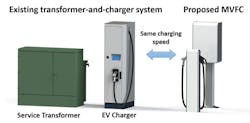
The table compares the characteristics of today’s state-of-the art EV battery charger with the proposed MVFC. And Figure 1 compares the size of the state-of-the-art and MVFC chargers.
1. Comparison of the state-of-the art system, which employs a service transformer and EV charger, and the proposed MVFC.
Conventional, 50-kW state-of-the-art chargers include a distribution transformer, which weighs 1000 kg, and a separate fast charger unit, which weighs 200 to 600 kg. To support the weight, this transformer-and-charger system usually needs to be installed on a concrete slab.
In contrast, the MVFC doesn’t employ a distribution transformer, but takes power directly from a utility medium-voltage line and converts it to dc, to be compatible with the electric vehicle’s battery.
“Our 50-kW MVFC weighs only around 100 kg and can be wall- or pole-mounted,” says Srdjan Lukic, an associate professor of electrical engineering at NC State and one of the researchers who developed the technology. “The MVFC does the work of both the transformer and the fast charger, taking power directly from a medium-voltage utility line and converting it for use in an electric-vehicle battery.
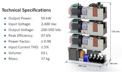
“This new approach offers 4X more power from the same system footprint, reducing the system installation costs at the same time,” says Srdjan Srdic, a research professor at NC State who also worked on developing the technology. Figure 2 shows a developed MVFC system with basic technical specifications.
2. MVFC power stage whose volume is 63L (119L packaged).
At present, the best transformer-and-charger stations are reported as having an efficiency of up to 93%, meaning that at least 7% of the power is lost to heat during the charging process.
In testing, the prototype MVFC has an efficiency of at least 97.5%, meaning an additional 4.5% of the power is used to charge the vehicle, rather than being wasted as heat. This reduces operating costs, increasing revenue without increasing the cost to consumers. “In other words, we were able to cut the wasted energy by more than 60%,” says Srdic.
The researchers were able to make the technology so much smaller, in part, because they used wide-bandgap semiconductor devices. This also made the technology more energy-efficient.
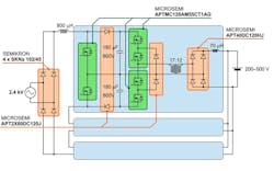
3. The MVFC power-stage circuit employs SiC power MOSFETs and diodes.
Figure 3 shows a simplified MVFC circuit that uses SiC power devices. The SiC devices are from Microsemi Corp., a subsidiary of Microchip Technology Inc. They include:
- APTMC120AM55CT1AG power module: Two SiC power MOSFETs (VDSS = 1200 V; RDS(ON) = 49 mΩ max @ TJ = 25°C; ID = 55 A and PD = 250 W @ TC = 25°C) and two SiC Schottky diodes (zero reverse recovery and zero forward recovery)
- APT2X60DC120J dual anti-parallel SiC diode power module: VRRM = 1200 V; IF = 60 A @ TC = 100°C; zero reverse recovery; zero forward recovery; ISOTOP package (SOT-227)
- APT40DC120HJ SiC diode bridge power module: VRRM = 1200 V; IF = 40A @ TC = 100°C; zero reverse recovery; zero forward recovery; ISOTOP package (SOT-227)
- Semikron SKNa 102/45: High-voltage stud silicon power diodes configured as a full-wave bridge
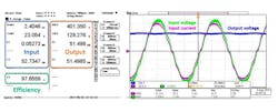
The current version of the MVFC charges at the same speed as existing charging stations because the MVFC was designed to operate at 50 kW, which is the power level of a typical fast charger (Fig. 4). The system can be scaled up to provide substantially higher power and connect to the three-phase MV line.
4. Experimental test results at rated input and output voltage and rated power.
Next Generation
The research team is in the process of building a next-generation MVFC that handles much higher power, capable of charging more vehicles and charging them more quickly.
“We’ve had the more powerful, multi-vehicle MVFC in mind for some time, and recently received funding from the Department of Energy to build a next-generation prototype,” says Lukic, who is the deputy director of the FREEDM Engineering Research Center at NC State.
In the multi-port station design, a utility line is connected directly to a solid-state transformer, (SST), which is a power-electronics-based smart transformer. The SST then feeds a local dc microgrid, with battery storage systems and multiple charging nodes that vehicles can plug into.
“We are building five charging nodes into the prototype, but there could be twice as many or more,” says Lukic.
The multi-port MVFC will have a rating capacity of 1 MW, with each charging node capable of providing up to 350 kW of power. The upgrade from 50 kW to 350 kW means that a vehicle can be charged up to 7X faster.
“We’re currently looking for industry partners to help us move from our fully functional prototypes to the marketplace,” says Lukic.
The development of the existing MVFC prototype was done with support from the PowerAmerica Institute, a public-private research initiative housed at NC State and funded by the DoE’s Office of Energy Efficiency and Renewable Energy (EERE). The development of the multi-vehicle MVFC prototype is being funded by EERE. FREEDM was created with support from the National Science Foundation.
About the Author

Sam Davis
Sam Davis was the editor-in-chief of Power Electronics Technology magazine and website that is now part of Electronic Design. He has 18 years experience in electronic engineering design and management, six years in public relations and 25 years as a trade press editor. He holds a BSEE from Case-Western Reserve University, and did graduate work at the same school and UCLA. Sam was the editor for PCIM, the predecessor to Power Electronics Technology, from 1984 to 2004. His engineering experience includes circuit and system design for Litton Systems, Bunker-Ramo, Rocketdyne, and Clevite Corporation.. Design tasks included analog circuits, display systems, power supplies, underwater ordnance systems, and test systems. He also served as a program manager for a Litton Systems Navy program.
Sam is the author of Computer Data Displays, a book published by Prentice-Hall in the U.S. and Japan in 1969. He is also a recipient of the Jesse Neal Award for trade press editorial excellence, and has one patent for naval ship construction that simplifies electronic system integration.
You can also check out his Power Electronics blog.
