Modern, high-end cars require almost 100 electronic control units (ECUs). Each ECU (Fig. 1) is powered from the car battery through a front-end buck converter. Back-end point-of-load (POL) buck converters, in turn, power the ECU’s smart loads (MCU, CAN, I/Os) with the low voltages required by each. These back-end voltage regulators must be small, adhere to tight safety standards, operate with low input voltages across a wide range of temperatures, and minimize radio frequency interference (RFI) while exhibiting high accuracy, high efficiency, and high reliability.
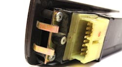
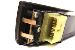
1. An electronic window control unit is an example of a type of ECU that’s powered through a front-end buck converter.
ECUs in the Car
ECUs are small computing modules that control most of the systems in a modern car. Accordingly, the on-board power electronics need to use minimal space. ECUs are connected via a controller area network (CAN) to control the car's engine, power windows, brakes, airbags, lights, entertainment system, steering functions, and more.
Powering the ECU
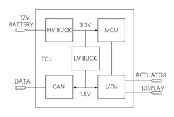
The block diagram of a typical ECU is shown in Figure 2. A front-end high-voltage buck converter (HV BUCK) interfaces directly to the car battery to power the MCU. Its output voltage is then distributed to the other ECU’s electronic loads via dedicated low-voltage POL buck converters (LV BUCK). ECUs pack a lot of electronics in a small space.
2. Here’s a block diagram of a typical ECU.
The Automotive Environment
The automotive environment is harsh, with wide swings in temperature and humidity, and constant exposure to chemical, radiative, and mechanical stresses. In this environment, functions like radio and other sensitive electronics must still correctly function. The switching regulators in the car must operate without adding electromagnetic pollution to this environment. They must also operate efficiently to reduce ECU heat generation, improving reliability.
Low Input and Output Voltage
The electronic loads in automobiles are designed with dense, submicron process technologies that require very accurate and very low voltages for operation. Depending on the process utilized, the ICs require diverse input voltages, from sub-1-V up to a few volts. Accordingly, the LV BUCK feeding these loads must operate with low input voltages from the HV BUCK, while delivering a regulated output that while low, covers a wide range of values.
Meet Automotive Standards
It can be difficult to find a single voltage regulator that meets all of the stringent requirements of automotive ECUs. These buck converters must be designed from the ground up to perform in an automotive environment. A low-input supply voltage poses the first challenge, as the LV buck internal circuitry must operate with little headroom.
Such a challenge is addressed with special low-voltage IC design techniques. High-frequency switching avoids AM-band RFI. Spread-spectrum modulation can further reduce EMI to help designs comply with stringent EMI standards such as CISPR25. Digital outputs reporting fault conditions to the supervisor systems are necessary to maximize system reliability.
The ICs must be manufactured and quality-tested beyond the level of consumer devices to meet automotive reliability requirements. Devices are characterized across the full automotive operating temperature range. Source dies are tracked and go through sorting to ensure the highest quality.
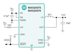
The MAX20073/MAX20074 switching regulator family (developed by Maxim Integrated) meets automotive standards and delivers 2-A/3-A load current from 0.5 to 3.8 V. The devices operate from a 2.7- to 5.5-V input voltage range, and over the -40°C to +125°C temperature range. Figure 3 shows the application diagram. The fixed-frequency pulse-width-modulation (PWM) mode of operation with a 2.2-MHz switching frequency (above the AM band) reduces RFI. An optional spread-spectrum mode is available to meet EMI requirements.
3. Shown is the application diagram of the MAX20074 and MAX20074.
Other features include:
Skip-mode operation
A highly efficient pulse-frequency modulation mode (skip mode) greatly improves efficiency at light loads. Skip mode reduces the switching frequency to the minimum required to maintain the output voltage. Skip mode can be activated/deactivated through a digital input on the IC.
High efficiency
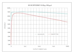
The family’s low RDS(ON) and integrated synchronous rectification MOSFETs contribute to high-efficiency operation. Efficiency remains high over a wide range of currents thanks to skip mode at light load and constant-frequency PWM operation at heavy load. The 2-A efficiency curve, with a 3.3-V input and 1.8-V output, is shown in Figure 4 (teal curve).
4. The teal curve shows the 2-A efficiency curve, with a 3.3-V input and 1.8-V output.
The IC’s efficiency across the entire operating range is shown to be higher than that of a competitive device (red curve). At full load (constant-frequency PWM operation), the 20 points of efficiency advantage is at a maximum.
Small size
The devices are available in a 3- × 3-mm, 10-pin TDFN package with an exposed pad. They use very few external components. A complete fixed-output circuit can fit into a 65-mm² area on a PCB.
Conclusion
Providing a combination of reliability, low-voltage input and output operation, small size, low noise, and high efficiency in automotive ECUs can be challenging. Two POL buck converters (2 A and 3 A) have been designed to meet the challenge—their fixed-frequency PWM operation, with a 2.2-MHz switching frequency, helps reduce RFI and spread-spectrum operation to meet stringent EMI standards. And the small package size and limited external components are important due to the decreasing amount of space available for automotive electronics.
Factory trimming also plays a key role in supporting fixed-output voltage values between 0.5 and 3.8 V in 25-mV increments. Alternatively, configuring the device to regulate to a voltage set by an external resistive divider is also possible. Such features make it easier to design compact, high-performance ECUs for harsh automotive environments.
