So…The K2-W Analog Computer Op Amp Has Mad Scientists’ Fingerprints on It (Part 1)
What you’ll learn:
- Bob Pease and Walt Jung provide an excellent overview of the K2-W’s circuit design.
- Philbrick Researches’ K2-W is a very-high-gain op-amp design using only two vacuum tubes.
- There’s a sweet book on Op Amps that’s available for free download from Analog Devices.
K2-W's first stage
Is not described anywhere
Let’s dig into it
The first commercially available op amp, known as the K2-W, was targeted for use as a basic building block in analog computing. The genius of George Philbrick and his design engineers was not in having the best specs, as Bob Pease excused in his columns, but in being good enough for the job. This, and improved reliability and very low cost, is what lead to large-scale adoption of analog computing for commercial applications in the 1950s and 1960s.
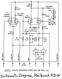
With several dozen op amps in an Analog Computer, the cost and complexity of each op amp needed to be reduced for commercial applications, unlike the previous military use of op amps as key elements for computing and directing large guns for the military. The minimalist design of the K2-W magically gets by with two 12AX7 high-mu, double-triode, vacuum tubes; a handful of resistors; a few caps; and a couple of cheap neon glow lamps, as can be seen in Bob’s schematic in Figure 1.
Bob discusses the K2-W’s circuit design and the operation of the second and third stages in detail in Part 2 of his K2-W writeup:
“The balanced input stage went to a single-sided level shifter down to the grid of the second stage, down near +2 V. This stage gets positive feedback from the output follower, via 221 kΩ, which was required to get the gain up from 4000 to 20,000. Note also the 15-pF Miller capacitor around the second stage, and the two NE-2 neon lamps used as level-changers to the grid of the output follower.”
Pease also mentions Electronic Design alumnus Walt Jung’s “new," now-highly-regarded book, Op Amp Applications, published by Analog Devices (the entire book, ISBN: 9780750678445, is available for a free, legit, PDF download here). It has a really well-researched history on Op Amps in Section H of the book, and includes a page dedicated to the K2-W. Walt’s description of the K2-W appears to have proliferated on the internet, with an excerpt describing circuit operation as follows:
“The K2-W used two 12AX7 dual triodes, with one of the two tubes operated as a long- tailed pair input stage, which offered fully differential operation at the input. With the K2-W operating on ±300V supplies, the input stage's 220kΩ tail resistor was returned to the –300V supply, fulfilling the long-tailed pair biasing requirement.
Half of the remaining 12AX7 dual triode was operated as a second gain stage, which in turn drove the remaining section as a cathode follower output, through a level shifter part 8355037 (typically thyrite devices). Overall gain of the K2-W was enhanced by positive feedback through the 150-kΩ resistor, connected back to the cathode of the second stage.”
Neither Bob, nor Walt, offer any theories on why its particular input-stage topology was chosen for the K2-W, merely noting that it was either “fully differential operation,” which I submit it is not, or that it was a balanced input stage, which I also submit it is not.
They also don’t go into any detail on how the input stage of the K2-W works, though Walt does provide a copious compendium of difficult-to-find reference material that likely has a description of the input circuit as prior art. If you’re aware of legit links to any of Walt’s ancient reference materials, please post them in the comments and I’ll try to add them into this blog.
I submit that the K2-W’s rather interesting input-stage design was the pivotal design decision that enabled Philbrick to use only two, jellybean, 12AX7 vacuum-tube triodes, instead of a greater number of tubes or more expensive pentode devices.
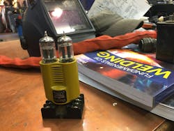
The ability to create a full-function operational amplifier with decent open-loop gain and load-driving capability with only two tubes and a handful of passives lent itself not only to very low cost and improved reliability, but also to an interesting packaging arrangement: The two tubes stood on an octal pinned base that was commonly used by relays at the time, with my own K2-W (notice the mismatched tubes - a 12AU7 and a 12AX7) on a base shown in here in Figure 2.
This package occupied a volumetric space similar to that of an octal-based switching relay. The octal base packaging strategy went so far as Philbrick suggesting the use of relay racks as the mechanical foundation for the creation of bespoke analog computers. Many of the “analog bricks,” which performed operational functions, were built by Philbrick, typically using three K2-Ws in each unit.
I picked up that K2-W from eBay recently, in anticipation of analyzing, demonstrating, and tearing it down for you here. But the seller substituted the tubes from those in the listing pic to where it was shipped with a 12AU7, a medium-mu dual triode, in place of one of the high-mu 12AX7 pairs. Ugh…that won’t make the OL gain we need for an op amp.
The replacement 12AX7s from that seller are still in “the check’s in the mail” status, as I’m forced to meet my publication deadlines. I also picked up a few more K2-Ws, from overseas, that should arrive in June.
So, the show must go on and, with apologies to Bob Pease, I'll need to resort to using SPICE in next week’s1 Part 2….
via Rako Studios Youtube Channel
Bob Pease has had it with SPICE simulations’ outputs.
References
1. I’ve committed to publishing my blog on the first and third Monday of the month, but this one blew out in word count. It’s written, so the three parts will appear a week apart, with part three showing up in the first Monday slot in June.
2. I popped over to my buddy Dave Williams’ Weldtight welding school, since he’s the only one I know with more tools than I have, to discuss a strategy for cracking open the K2-W for a teardown (coming in a future blog). Dave disappeared into the backroom and came back out with that octal relay socket adapter his father, an engineer at Tek’, had picked up at the Tektronix Country Store years ago. Mind blown that it would appear in a welding shop.
