So...Analog Computers Turn THAT Lorenz Attractor into Child’s Play (Part 3)
What you’ll learn:
- Anabrid’s THAT Analog Computer provides a flexible, programmable, quick way to perform computations on equations.
- What is a Lorenz Attractor and other “strange attractors”?
- Analog computations can be set up by kids ranging from 8 to over 100 years old.
- Analog computing can be performed with dedicated circuit designs.
- Other methods can be used to compute strange attractors.
“Lorenz Attractor”
That’s what you chose in our poll
Here you go, as asked
No, the image at the head of this page is not Star Trek’s Enterprise NCC-1701L—it’s a ray-traced Lorenz Attractor plot. A Lorenz Attractor was chosen as an analog computing patch by readers in the poll in Part 1 of this three-part series on THAT, an affordable Analog Computer made by Anabrid Gmbh and graciously provided by them, which enables the demos we’re doing in this blog.
The Lorenz Attractor (“LA”) is based on a series of coupled differential equations that were described by Edward Lorenz in his 1963 atmospheric modeling paper, where one differential equation affects another by using the other equation’s integral as a variable.
The following description is largely “borrowed” from Anabrid: The Lorenz Attractor system is described by three coupled differential equations (x' is Lagrange notation the first derivative of x with respect to time):
x'=σ(y-x)
y'=x(ρ-z)-y
z'=xy-βz
The parameters are σ=10 (Prandtl number), β=8/3 (the cell geometry underlying the model), and ρ=28 (relative Rayleigh number). Scaling and rewriting the equations produces the following:
x=∫1.8y-x dt+C
s=1-2.678z
y=∫1.5556xs-0.1y dt
z=∫1.5xy-0.2667z dt
The constant C represents the initial condition of that integrator and isn’t critical. Since each integrator and summer performs an implicit change of sign in an analog computer, such as THAT, the above equations can be simplified:
-x=-∫1.8y-x dt+C
-z=-∫1.5xy-0.2667z dt
s=-(1-2.68z)
r=-xs
-y=-∫1.536r-0.1y dt
These equations can now be implemented directly on an Analogue Computer as shown in the patch schematic from the THAT Analog Computer user manual (Fig. 1a).
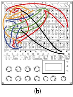
Figure 1b shows the corresponding patch diagram, from the THAT User Manual.
Programming Analog Computers for Vitamin D Production
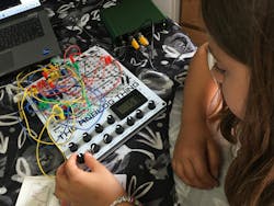
When my 8-year-old engineering apprentice was asked if she’d also like to patch THAT for the Lorenz Attractor, she enthusiastically agreed, based upon her work on the Automotive Suspension analog computation. However, she had terms to be satisfied: She asked if she could patchcord THAT, outside, on a nice sunny day (WFL: Work From Lawn) (Fig. 2).
My minion came up with that great modeling pose herself (she loves tech and gearhead stuff, and playing chess, but still retains her girly sensibilities), and it’s a pic that I’ll likely print as an 11x17 and frame. But not wanting to deal with her agent, her modeling agency, her royalties and doing taxes on those; with Electronic Design’s legal team, and with her being hounded by 8-year-old Analog Computer aficionados for autographs, I decided to crop that pic for use here. Sorry, ask me for a look next time you see me at a tradeshow or other meetup.
We’re still using the ADP2230 USB oscilloscope for the THAT Lorenz Attractor analog computation, graciously provided by Digilent on my request. The use of my laptop as a scope display was not very sunlight readable, so it was back inside to minion’s kitchen table to power THAT up.
Running an Analog Computer is Child’s Play
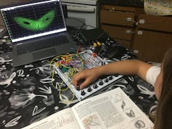
Here you see our minion setting one of the six coefficients using the “COEF” selector switch and turning the associated potentiometer (Fig. 3). She was a stickler for getting the embedded voltmeter accuracy to all decimal places on its display, which is possible with a delicate touch on THAT’s single-turn pots.
After she got the coefficients all set up, my young apprentice turned the mode switch from “Coeff” to “Rep” (which repeats the IC initial conditions and OP operate functions automatically); I set up the USB scope for her in x-y display mode on the laptop. The outputs were set to observe the Analog Computer’s x and z outputs and look like that in Figure 4, pre-twiddle.
We also made a video of her twiddling Coefficient 1, though some video frames were sadly lost in shortening the video file size (Fig. 5).
5. Video showing the effect of Coefficient 1 being changed.
I Did It Bob’s Way
In Part 2’s automobile suspension analog computation, we had our young minion patch the THAT’s programming. Additionally, we referred to Bob Pease’s Analog Computing approach, where he built the Analog Computing solution using op amps and discrete components. In the absence of a quickly patched “programmable” Analog Computer such as THAT, we also would need to construct a computer from relatively common components to compute the Lorenz Attractor equations.
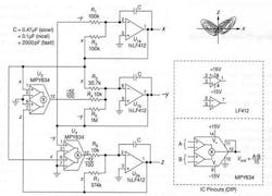
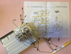
Again, I’m not lazy, just efficient with my time and don’t believe in reinventing the wheel, so we’ll use the Lorenz Attractor circuit found in Paul Horowitz’s highly regarded book The Art of Electronics. No, not that one. There are a couple of his books that bear the same title, so buyer beware—the following Lorenz Attractor circuit is from Horowitz’s (& Hill’s) subsequent The Art of Electronics: The x-Chapters (2020), which is chock full of nice application circuits (Fig. 6).
Staying Faithful to the X
In order to remain faithful to the Horowitz & Hill x-Chapters design, I ordered the components as specified in their schematic, despite the sticker shock1 I got from the 4-quadrant multiplier chips (at least the multipliers haven’t also been shrinkflated by the MBAs to 3.75-quadrants...) by way of a component distributor.
Freshly delivered a day before my publication deadline, I populated a breadboard (which is NOT Bob's way, and for good reason) with the components, powered the circuits with two bench supplies set to ±15 V AND used the Digilent USB oscilloscope (I did buy the accessories and Digilent’s new Discovery 3-specific “Canvas” breadboard2 afterwards).
Digilent's Analog Discovery Studio can provide programmable power supplies, has a fixed +/- pair of 12-V supplies easily accessd by their Canvas breadboard, and offers two oscilloscope channels of sufficient bandwidth for our purposes, but I only have the Canvas at this time.
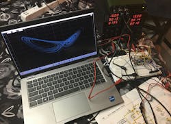
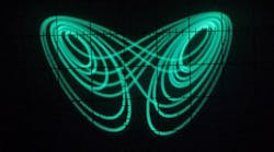
Firing up my setup gave us the following results (Fig. 7), though be warned that using a breadboard has all kinds of capacitance, potential ground loops, and crosstalk from the jumper wiring (Fig. 8), that may need to be worked through before the attractor behaves itself. Being a chaotic circuit, such quirky behavior in the presence of parasitics is expected.
Attractive Attractors
Attractors have become a bit of a hobby for many of us. Sariel Hodisan, who’s a Senior Hardware Engineer at Applied Materials, just recently designed a circuit board. The schematic PDF file is attached below, which he has asked everyone to freely share—it features three types of attractors, (Lorenz, Chua, and Rossler) implemented in discrete analog components.
Note that the THAT Analog Computer can be patched to do all of Sariel’s “strange attractors” as well. As of the publication deadline, I haven’t seen Sariel’s bench results for the board.
The Wikipedia reference I provided above does have source code for various computer languages if you really must do your Lorenz Attractor on a digital computer.
One forgivable software approach created the lede image we used for this blog by using POV-Ray to generate poster-worthy Lorenz plots. Thanks to Mitchell Richling, whose day job is HPC Architect at Texas Instruments, for allowing Electronic Design to use that image—you’ll find more details and the source code on his web page here. Mitchell also has an LTSpice deck and source code for several digital languages for Lorenz Attractors on that page.
Having dropped 80 bucks on components and shipping to breadboard the Lorenz Attractor (not counting the power supplies and breadboard), the flexibility, quick implementation, integration, and low cost (there’s a discount code in Part 1 of this series) of the THAT Analog Computer still makes the most sense to me. Especially considering that you can engage a kid of any age with programming it. My minion got intimidated at breadboarding Horowitz & Hill and perked up when I told her I still had THAT in the car—breadboarding an attractor is NOT child's play both in her opinion and in mine.
All for now,
-AndyT
Andy's Nonlinearities blog arrives the first and third Monday of every month. To make sure you don't miss the latest edition, subscribe to our Electronic Design Today newsletter.
References
1. This position I have at Electronic Design is “technology editor,” where we write about stuff for our readers. We don’t get an engineering budget to build anything—it’s either graciously provided by suppliers on request (which I note and try to be gracious about) or it’s a spend out of my own pocket. Bob Pease was blessed when he wrote his bimonthly Electronic Design columns because he was also an employee at National Semiconductor at the time. So, he had lab equipment and parts available at his whim, just as we all do as engineers at our employers’ facilities. I also want to thank Bill W., Alix P., James M., Cabe A., and Roger E. for picking up the other “texty” editor work that I’m not doing during the times I do this engineering stuff to write about. It’s really a team effort for me to be able to do this blog with hands-on engineering, so please give them a golf clap for enabling Electronic Design to do this kind of content.
2. Speaking of breadboards, the Sandwizz Schematic-programmed breadboard’s Kickstarter campaign ends [ended] this week on Friday July 19, 2024 at 6 am PDT.
About the Author
Andy Turudic
Technology Editor, Electronic Design
Andy Turudic is a Technology Editor for Electronic Design Magazine, primarily covering Analog and Mixed-Signal circuits and devices. He holds a Bachelor's in EE from the University of Windsor (Ontario Canada) and has been involved in electronics, semiconductors, and gearhead stuff, for a bit over a half century.
"AndyT" brings his multidisciplinary engineering experience from companies that include National Semiconductor (now Texas Instruments), Altera (Intel), Agere, Zarlink, TriQuint,(now Qorvo), SW Bell (managing a research team at Bellcore, Bell Labs and Rockwell Science Center), Bell-Northern Research, and Northern Telecom and brings publisher employment experience as a paperboy for The Oshawa Times.
After hours, when he's not working on the latest invention to add to his portfolio of 16 issued US patents, he's lending advice and experience to the electric vehicle conversion community from his mountain lair in the Pacific Northwet[sic].
AndyT's engineering blog, "Nonlinearities," publishes the 1st and 3rd monday of each month. Andy's OpEd may appear at other times, with fair warning given by the Vu meter pic.


