New Gear Accelerates And Simplifes 100/400-Gbit/s Optical Testing
As electronic communications circuits and systems become more complex and critical, testing grows far more difficult. Also, new standards impose unusually demanding specifications that take time to validate. One key outcome is a significant increase in production test time that is now a big part of the cost of any new product.
This file type includes high resolution graphics and schematics when applicable.
This certainly is the case with new 100/400-Gbit/s fiber-optical components and products. These super-high data rates present a challenge not only in research, design, and development but also in production. Tektronix’s optical test solutions, which mix new products, existing products, and product enhancements, simplify and speed up optical testing.
100-Gbit/s Testing
The demand for ever-faster Internet access continues to increase along with mobile data speed and volumes thanks mostly to video applications. Ever-faster fiber-optical networks in long-haul, short-reach, and backhaul systems are addressing the need for extra speed. While 10-Gbit/s systems are common, more carriers and companies are upgrading to 40-Gbit/s and 100-Gbit/s systems. New components and products are now available to meet the demand.
Several different standards support the 100-Gbit/s rate. For short-haul applications such as data centers, disk arrays, private local-area networks (LANs), and metro networks, Ethernet 802.3 standards are usually used. For example, Ethernet 100GBASE-R4 uses four parallel multi-mode or single-mode fibers, each with a data rate of 25 Gbits/s (25.78 Gbits/s actual). Sonet OTU4 uses four parallel fibers to deliver 25 Gbits/s (27.95 Gbits/s actual).
Another common test need is shorter electrical connections in optical switches, routers, and transport or data center equipment. The Optical Internetworking Forum (OIF) has common electrical interface (CEI) standards called implementation agreements (IA) that define 4x25G links over backplanes or from chip to chip or chip to module. The most common are CEI-25G-LR (long reach) and CEI-25G-VSR (very short reach), which present their own test challenges.
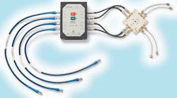
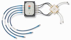
For electrical 4x25G testing of chipsets, transceivers, or systems, a standard set of instruments is used. For signal generation, either the PPG3204 pattern generator or the BSA286C BERTScope can be used. The test signal is then sent to the new LE320, a 32-Gbit/s, two-differential channel, nine-tap linear equalizer, for receiver testing (Fig. 1).
The device under test (DUT) gets the LE320 enhanced signal, and the DUT output goes to one of several display options: the PED4000 error detector, the BSA286C BERTScope, or the DSA8300 sampling oscilloscope. Software for analysis includes the JMAP bit error rate (BER) contour and jitter analysis, the 80SJBN jitter and timing analysis, or the CEI-VSR compliance test.
The need for 4x25G testing is becoming more important as the industry moves from silicon design to transceiver and system design. Designers are creating network elements that allow data rates up to 100 Gbits/s, which will be delivered using four lanes of 25 to 28 Gbits/s. Design challenges emerge when transmitting these high frequencies on printed-circuit boards (PCBs), even for short distances.
The key to successfully testing such systems is the LE320, which provides test engineers with versatile output signal conditioning and tunable input equalization to create an optimal system for testing four electrical channels operating at 25 to 28 Gbits/s each. The Sampling Oscilloscope Option CEI-VSR will help to ensure efficient and consistent compliance testing support so designers can smooth the transition to manufacturing.
Designers developing systems that run at 10 Gbits/s or faster need an equalizer in front of receiver inputs or a pre-emphasis module on transmitter outputs. As speeds increase, designers have had a limited selection of signal conditioning products beyond 12 Gbits/s for meeting these requirements.
The LE320 supports signal conditioning on data rates from 8 to 32 Gbits/s in a nine-tap design used to deliver the high-precision error rate testing required by 100G communication standards like CEI-28G-VSR. Its remote head design enables designers to minimize cable length in their test system and avoid signal degradation issues, which are significant at 25 to 28 Gbits/s. With programmable equalization, the LE320 can be configured to provide standards-specific equalization, permitting BER analysis on otherwise closed eye signals.
Multi-lane, high-data-rate standards are driving the need for multi-channel BER instruments. Stressed receiver tests, four-channel end-to-end BER testing, and crosstalk tests are now among the suite of tests driven by the move to multiple high-speed parallel lanes.
Jitter measurements are also a major part of 100-Gbit/s electrical testing. The Tektronix PPG/PED line of multi-lane BER testers (BERTs) has been enhanced to provide expanded jitter impairment capability, new output adjustment flexibility, and higher-speed error detection capability to better meet the requirements of these standards.
The extended range of jitter insertion options includes option HFJIT, which now provides BUJ as well as RJ and SJ; and high-amplitude/ low-frequency PJ as part of new option LFJIT. Option ADJ adds adjustable outputs with fast rise/fall time and low intrinsic jitter required for 32-Gbit/s multi-channel pattern generator applications. The PED4000 series of error detector products, which are capable of data rates of up to 40 Gbits/s in one- or two-channel configurations, has enhanced data-rate margin testing.
The IA for OIF CEI 3.0 specifies the tests and limits for devices based on OIF standards. CEI-28G-VSR, which is one of those standards, is intended for use in very short-reach electrical channels in pluggable optical transceivers. These electrical interfaces must be able to meet system BER targets and undergo rigorous testing and debug cycles.
Until now, performing all the required tests for CEI-28G-VSR compliance and isolating problems related to jitter or noise has been difficult and labor intensive. Integration with Tektronix 80SJNB serial data link analysis software enables deeper debug and timing root cause analysis without the need to move to a different instrument or measurement setup.
By using Option CEI-VSR with the Tektronix DSA8300 sampling oscilloscope, design engineers can perform compliance measurements in less than 5 minutes, reducing their testing time by approximately 95% compared to manual alternatives.
100/400-Gbit/s Optical Testing
High-speed optical networking is increasingly being used for short-reach data-center applications, creating a need for test equipment to support analysis of multi-mode, 850- and 1310-nm signals found in 100Gb (4x25) Ethernet systems. For long-haul applications, designers are turning to coherent modulation techniques to get the most from available fiber bandwidth, creating a need for test systems to help ensure optimum performance and low BERs using formats such as dual-polarization quadrature phase shift keying (DP-QPSK), polarization-multiplexed QPSK (PM-QPSK), and polarization-multiplexed 16-phase quadrature amplitude modulation (PM-16QAM).
To address this problem, the 32-GHz 80C15 multi-mode optical sampling module for use with DSA8300 series sampling oscilloscopes provides high-quality acquisition of 850- and 1310-nm multi-mode signals. With a tightly controlled frequency response, it enables repeatable automated compliance testing for all of the short-reach standards from 22 to 32 GHz.
The combination of a DSA8300 series mainframe and an 80C15 multi-mode optical sampling module delivers ultra-low instrumentation noise and phase noise (jitter) for <100-fs RMS electrical and optical jitter measurements. It delivers the test margin needed to accurately measure the low-power signals used in short-reach applications. It also supports mask testing including mask margins based on standard specified hit ratios.
For long-haul applications, the OIF’s DP-QPSK technique over single-mode fiber is the de facto standard using the optical transport network (OTN) protocols. DP-QPSK is a modulation technique that effectively quadruples the data rate over standard on-off keying (OOK) of the laser in systems using 10 Gbits/s or less.
QPSK transmits two bits per symbol or baud as it combines two carriers of the same light frequency with a 90° phase shift between them. Then the two QPSK signals are multiplexed on a single fiber by transmitting one QPSK signal with a horizontally polarized orientation and another QPSK signal is transmitted with vertical polarization. The combination of QPSK and dual polarization produces a fourfold increase in data rate over OOK, allowing a lower clock rate at 25 GHz to be used.
The receiver uses coherent demodulation, meaning the DP-QPSK signal is mixed with a local oscillator signal at the clock frequency allowing the receiver to sync in both frequency and phase to recover the bits. This coherent detection also helps mitigate optical impairments like chromatic and polarization mode dispersion. It also improves the signal-to-noise ratio, allowing longer fiber reaches to be used.
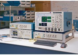
The AWG70001A arbitrary waveform generator generates the signal in the test setup for long-haul coherent modulation testing (Fig. 2). The PPG3204 32-Gbit/s pattern generator also may be included. The generated signal is sent to the OM5110 multi-format optical modulator and transmitter. The transmitter drives the fiber cable to the receiver, the OM4106D coherent lightwave signal analyzer.
The output is viewed on the DPO73304DX digital phosphor oscilloscope. The MSO73304 33-GHz oscilloscope also may be used. The OM1106 optical modulation analysis software analyzes the signal. Once the test setup has been adjusted for the test, the transmitter or the receiver is replaced with the device to be tested.
For long-haul optical research and development applications, the OM5110 modulates all common formats including binary phase-shift keying (BPSK), PM-QPSK, and PM-16QAM up to 46 Gbaud with fully automated and manual bias control of modulator and RF amplifiers, giving users complete configurability and versatility. With the introduction of the OM5110, Tektronix is the only test and measurement vendor that offers a complete coherent optical test system from signal generation to modulation, acquisition, and analysis.
The OM5110 offers built-in C or L band lasers along with support for external lasers. Automatic bias control allows for quick setup and easy operation of the modulator, while the manual bias control capability enables users to take control of all bias voltages for testing specific scenarios.
The AWG70001A 50-Gsample/s arbitrary waveform generator and the OM5110 make up a complete coherent optical signal generation system that’s ideal for the design of the most effective coherent modulation formats. By adding an optical modulation analyzer and oscilloscope, such as the OM4106D coherent lightwave signal analyzer and DPO73304DX digital phosphor oscilloscope, engineers have access to a complete, end-to-end coherent optical test system.
The next challenge is testing systems beyond 100 Gbits/s. Already in demand, new standards and products for 400 Gbits/s, 500 Gbits/s, and 1 Tbit/s are being developed. These rates will be achieved with multiple wavelengths multiplexed on a single fiber. New systems will use two, five, eight, or 10 light carriers using coherent modulation schemes like DP-QPSK or DP-16QAM. Formal standards have yet to be set. Tektronix’s optical test systems can support that coming challenge.


