QUESTION: There are so many different voltage regulators on the market these days. How do I pick one that will be good for my circuit?
ANSWER: Wow, this is a tough question, but also a good one. I’ll try my best to answer it concisely. Figures of merit are generally used for such decisions as they provide a quantitative comparison. Neglecting the cost for the moment there are seven significant figures of merit to consider.
FIXED OR ADJUSTABLE
Voltage regulators are available with fixed or adjustable output voltage. If you don’t need to trim the output voltage or adjust it to a non-standard voltage then the fixed voltage regulator will use less parts and so is often the better choice.
DROPOUT VOLTAGE - LINEAR REGULATOR OR (U)LDO
Many engineers believe these are the same. They are not. A linear regulator typically requires a minimum of 3 volts difference between the input and output voltages. Low dropout regulators generally require less than 1V differential and ULDO’s require much less, with some as low as 35mV.
MAXIMUM OUTPUT CURRENT
The regulator output current rating should be selected reasonably close to the maximum required current in the circuit. Lightly loaded regulators often end up with stability issues http://powerelectronics.com/power-management/no-load-specification-impacts-power-supply-performance. Also for the current limit circuitry in the regulator to be useful we don’t want to choose a device rating that is too high because the short circuit current will also be too high to protect the circuit.
VOLTAGE ACCURACY
Of course the reason for the voltage regulator is to make the voltage more accurate, but how accurate is accurate enough. This is circuit dependent. If you are using a regulator to power digital IC’s or opamps for example, the regulation requirement is often not a big concern and 5% is quite tolerable. If the voltage regulator is also being used as a reference voltage then the accuracy would be more important. Note that regulators and references are VERY DIFFERENT and not really interchangeable, but many low cost A/D converters use VDD also as the A/D reference.
PSRR
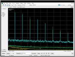
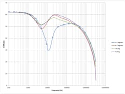
In the past the PSRR performance of LDO and ULDO regulators was poor compared with linear regulators. Technology is improving quickly in this regard, with many LDO’s and ULDO’s providing excellent PSRR performance. Of course the PSRR performance should be measured at the frequency of interest. Most devices are specified at 120Hz, and this is because in the past we used transformer rectifiers to create the input voltage to the linear regulators and the transformer rectifiers had ripple at twice the frequency of the AC mains. Today most linear regulators are connected to switching power supplies, and so the concern is at the harmonics of the switching frequency and any other noise sources at the regulator input. A better figure of merit is probably the product of PSRR and Frequency, much like Gain Bandwidth in an opamp. PSS can vary dramatically between voltage regulators as seen in Figure 1.
OUTPUT NOISE
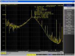
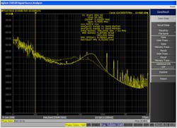
Unlike voltage references, linear regulators and LDO’s often have spurious responses, which will interfere with sensitive circuits, such as A/D clocks and LNA’s. This is one of the more important requirements and is generally not well specified, so plan on measuring several devices once you have narrowed down the choices a bit. Figure 2 shows the jitter of an ADC clock with noise spurs. These spurs are due to the noise of the regulator as well as the switching power supply ripple feeding through to the clock.
STABILITY
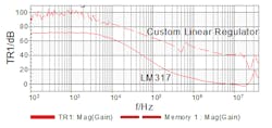
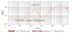
Typical datasheets don’t say much about the control loop stability, but the stability controls the closed loop performance of the regulator and so poor stability means poor performance. Many regulators provide a chart that shows the range of ESR for different capacitors, but there is not generally a quantitative assessment of the stability and so as with the output noise plan on measuring several devices once you have narrowed down the choices a bit. Figure 4 shows the output impedance of two voltage regulators. The LM317 has poor stability, identified by the sharp peak in the waveform while the custom regulator is very stable, lacking the sharp peak. Poor stability also degrades PSRR as seen in Figure 5. Typical applications I see in industry are in the 15 Degree to 25 Degree range, which is close to the worst curve in this figure.
OUTPUT IMPEDANCE
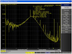
Figure 6 shows the jitter measurement of an ADC clock powered by each of the regulators in is shown in Figure 4. Note that the impedance peak from figure 4 can be seen in the clock jitter in Figure 6. The goal is flat impedance and with the smallest capacitors possible. This is for physical space reasons and also cost reasons, so the device with a lower output impedance is a better choice, but then you also need to be careful about ESR to keep it stable. Since this is not generally in the datasheet you need to plan on measuring several devices once you narrow down the choices a bit. As with PSRR the impedance figure of merit is likely more useful as Ohms/frequency, which you might recognize as being an equivalent inductance.
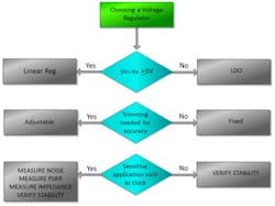
There are several independent decisions, shown in Figure 7. Since much of the data is not provided by the manufacturer, it is generally best to narrow the choices down using the decision tree and then test a few devices or have them tested for you. These measurements should be made either in circuit or with the output capacitors you intend to use and at the expected voltage regulator load current.
For application notes on any of these measurements, please visit www.picotest.com.
Do you have any questions about this article? If so, write them in the comments section below and I will respond as soon as possible.
About the Author
Steve Sandler
Steve Sandler is the founder and chief engineer of AEi Systems LLC and the president of Picotest. At Picotest he is responsible for signal injector product development, as well as the overall operation of the test equipment company.
