EMI control is another nonnegotiable consideration. Since electronic products incorporate faster components operating at higher frequencies than ever before, limiting unwanted emissions gets more and more difficult. This factor and the requirement to limit susceptibility to externally generated emissions make RF shielding necessary.
EMI problems are exacerbated by the move to lighter, less expensive enclosures. As a result, the choice of shielding is becoming more of a challenge for the designer of small consumer electronics.
Plastics offer the best prospects for lightweight packaging with EMI control. A polymer does not provide shielding, but it can be modified to do so using conductive plating, impregnation, paint, or spray. Each of these treatments is expensive, but the alternative of going back to metal enclosures is not an option.
Board-Level Shielding
Because attempting to prevent EMI problems by shielding the entire enclosure is so costly, since 1995 the telecommunications industry has encouraged the development of the board-level shield (BLS) for cellular phones. The typical BLS is a five-sided, custom-formed metal box mounted directly on the PCB. Shields are packaged in a tape-and-reel form to minimize assembly costs.
Shielding effectiveness of a BLS is quite dependent on the design of the PCB mounting area. Theoretically, the sixth side of the BLS cube is the ground plane on the board, so the number and spacing of vias and traces will affect the shielding. For that reason, just placing a shield over a device or circuit may not be effective if the sixth side is not considered in the shielding design.
Generally, a BLS is available with holes for thermal cooling. However, the shorter wavelengths of higher frequencies make the number and size of holes an issue. If a hole is even a small fraction of the operating wavelength, it lowers the shielding effectiveness of the BLS.
There is another issue—heat. Along with shielding, thermal dissipation is becoming a critical design factor, and it is extremely desirable to accomplish EMI control and temperature management with the same part. This isn’t easy. Today’s faster components generate a troublesome amount of heat, yet the ventilation apertures must be small to control the EMI.
Thermal Management—A Case History
One design team developed a new, high-performance telecommunications product recently and needed to suppress EMI and control the temperature of two digital signal processor (DSP) chips on a radio receiver. The extremely fast chips generated high levels of radiated energy and had to be shielded carefully to meet FCC and CE requirements. The conventional BLS offered a possible solution, but by itself couldn’t dissipate the heat satisfactorily.
The designers fastened a customized heat sink to the top of the DSP by using thermally conductive tape. This worked, but the high expense of the machined heat sink and the extremely labor-intensive assembly was totally unacceptable.
What about a snap-in shield? It would dissipate the heat, but its EMI suppression capabilities were not good enough. Was it possible to reconcile the seemingly incompatible challenges of simultaneous EMI control and thermal management? Fortunately, yes.
A New Type of Shield
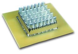
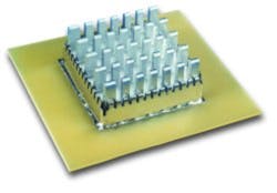
Two products developed by Laird Technologies solved the designer’s dilemma. Cool Shield I™ has a snap-in copper heat sink sized for use with new or existing BLSs, and Cool Shield II™ features a spring-finger fence that mates with a standard aluminum heat sink to surround a component or circuit as shown in Figure 1. Both have a five-sided enclosure for EMI control, and thermal management is achieved through the heat sink.
For maximum heat transfer, the base of the heat sink in each model has a double-sided, thermally conductive adhesive pad. When the product will be used in severe shock or vibration environments, heat-sink clips are included. In any case, the heat sink is removable for access to the components inside.
With the new shields, both EMI and thermal considerations for DSPs on the telecommunications product are under control. In addition, labor costs are minimized because the shields can be provided on a tape-and-reel for automatic installation.
Other Considerations in BLS
Even with the new BLS, the designers had to ensure that the heat sink didn’t radiate. As the operating frequency increases and physical dimensions become an appreciable fraction of the wavelength, energy is capacitively coupled from the component to the heat sink. As a result, it acts like a monopole antenna and transmits troublesome signals. Consequently, it is necessary to ground the shield.1 One study on the subject recommends a minimum of four ground points.2
The snap-in heat sink and finger fence used for EMI control on the telecommunications product are automatically grounded when the device is installed. As a result, there are no extra material costs, time, or labor involved when using the new BLS. Also, each heat sink is grounded around its periphery to prevent radiation.
Each of the shields acts as a lid over the related component and is held in place by double-sided thermal adhesive. If necessary, the heat sink can be removed to provide quick and easy access for component inspection and maintenance. Reinstalling the heat sink restores the original EMI and thermal protection.
The Bottom Line
The BLS technology of the past several years has reduced costs dramatically in manufacturing electronic products. However, the scenario is changing. Frequencies continue to go up, and this demands smaller ventilation holes. At the same time, components generate more heat and need larger openings to get more air. With these dueling factors, the solutions of a couple of years ago no longer are viable. EMI control must be intimately related to thermal management.
One telecommunications equipment manufacturer solved both the EMI and thermal problems with the new heat sink. And since the heat sink is grounded to the PCB, it doesn’t re-radiate.
References
- Montrose, M.I., Printed Circuit Board Design Techniques for EMC Compliance, IEEE Press, 1996.
- Li, Y.-L., Radhakrishnan, K., and Wittner, D., Study of Heatsink Grounding Schemes for GHz Microprocessors, IEEE 9th Topical Meeting on Electrical Performance of Electronic Packaging, Oct. 23-25, 2000.
About the Authors
Ed Nakauchi, principal scientist and consultant at Laird Technologies, holds a B.S.E.E. from Northrop University and an M.S.E.E. from Columbia Pacific. He has more than 30 years of electronics experience, the past 20 in EMI and ESD control, and has written design guides for U.S. Army, Air Force, and NASA programs. He leads seminars and teaches EMI courses through the extension program of the University of California, Irvine.
Mike Oliver is a product development engineer at Laird Technologies responsible for shielding development and test. He is chair of the ASTM D09.12.14 EMI Subcommittee, vice-chair of the SAE AE4 EMI Committee, and a member of the IEEE EMC Society and Standards and Advisory Coordination Committee.
Laird Technologies, P.O. Box 650, Delaware Water Gap, PA 18327, 570-424-8510, www.lairdtech.com.
Return to EE Home Page
Published by EE-Evaluation Engineering
All contents © 2001 Nelson Publishing Inc.
No reprint, distribution, or reuse in any medium is permitted
without the express written consent of the publisher.
August 2001

