Bipolar power supplies are specialized instruments that provide both positive and negative outputs. A unique feature of many bipolar power supplies is the capability to both source and sink power, that is, to operate in all four quadrants of an E-I plot.
The energy-absorbing elements are the output transistors. Such technology works well up to about 400 W, providing wide bandwidth, low noise, high control accuracy, and when working as a source, exceptional line and load stabilization.
The present challenge is to extend the concept of bipolar, four-quadrant power supplies to significantly higher power levels by using high-efficiency switch-mode conversion. The circuit topologies to produce efficient sources at these power levels are well established.
Less obvious is how to sink (absorb energy from an active load) without dissipating it. Dissipation is, of course, the antithesis of what switch-mode power supplies are all about and would defeat the whole reason to go to switch-mode conversion in the first place.
For example, in Kepco’s 1,000- and 2,000-W bipolar power supplies, the solution is recuperation. With this technology, energy sinked from an active load is passed backwards through the switch and the input power-factor correcting circuit to the AC power lines where it becomes available for re-use.
Operation
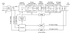
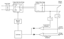
Figures 1 and 2 are block diagrams of a power supply with recuperation. When working in the source mode, the basic topology of the front end (FE) is a boost converter, current fed, with an isolating transformer.The following elements allow the design to work from an AC input source without rectification, which is mandatory for recuperation: • Capacitor Clamp Stage—functions as a pre-boost capacitor. • Primary Switcher Bridge—uses bidirectional switches (BDS), mandatory for recuperation. • Isolating Transformer—not only isolates, but also facilitates recuperation. • Input Signal Conditioner—prepares the signals related to input voltage value and polarity, input current value, and clamp capacitor voltage; providing valid information to the regular boost controller.
The controller performs active power-factor correction with average current-mode control. It controls the flow of energy from the input to the FE output DC bus through the isolating transformer, after which it is rectified by the secondary switcher bridge diodes and filtered by the FE output capacitor.The outer feedback loop of the controller maintains a constant FE output voltage. The direction of the FE output current indicates the mode of operation to the controller: either source or recuperation. All signal exchanges between the FE primary and the FE secondary are via transformers or optocouplers. The zero volt switching (ZVS) technique is used for the primary switches to reduce conduction losses and noise.
The power supply’s output stage basically is a class D power amplifier powered by the FE DC output voltage. It amplifies the voltage or current reference signals, depending on whether the unit is operating in the voltage or current mode, with an amplification factor established by Kv for the voltage mode or 1/(Ki × Rshunt) for the current mode.
The actual mode of operation— voltage or current—depends upon the correlation between reference signal values and load value. The controller is a classic pulse width modulator (PWM). It controls the flow of energy from the output capacitor of the FE stage to the bipolar output, through the output filter, which attenuates the switching- related frequencies. A soft switching technique is used for the output switches to reduce the conduction losses and noise.
When working in the recuperation mode, the load delivers the energy. The active load injects a current through the output stage, charging the FE output capacitor. As soon as that happens, the FE controller detects that the output current direction has changed.
The transfer of energy from the input source to the FE output ceases, and in a couple of switching cycles, the supply is prepared to recuperate the incoming energy from the FE output. The switcher matrix is configured so the FE has a buck topology with an isolating transformer, allowing the incoming energy to flow through the transformer, the primary bridge, and input inductor and into the input source.
Two primary bidirectional switches (either both A switches or both B switches) open when the corresponding secondary switches (both A or both B switches) diagonally are closed, allowing the energy to be stored in the input inductor. Consequently, all the primary switches are closed when the secondary switches are open, so the primary switcher bridge functions as a freewheeling diode. Then the energy stored in the input inductor is returned to the input source.
With the inner feedback loop, the controller monitors the FE input current to ensure that the current injected into the input source is 180° out of phase with the input voltage. With an outer feedback loop, the controller maintains a constant FE output voltage. The capacitor clamps the voltage coming through the transformer.
The more reactive the load, the more important is energy recuperation since the power involved is larger. The need to recuperate energy becomes more important as the reactive part of the load gets larger, the amount of power involved increases, or when either the load or the power supply output is variable. All these factors determine the amount of energy available to be recuperated.
Applications
The energy recuperation capability is a technology that enables high power, four-quadrant power supplies to use switch-mode technology for improved efficiency and reduced size and weight. Without recuperation, absorbed energy would have to be dissipated as heat. This dissipation would be impractical at the 1-kW level and above, such as in the following applications.
Power and Control of DC Motors The power required from motors in many automotive applications, such as power windows, seats, and hideaway headlights, is growing, and the testing of these motors must factor in a large amount of sink energy during motor slow-down time. A four-quadrant power supply using recuperation technology will allow greater numbers of such motors to be tested more quickly, without the correspondingly large increase in testrack space or power consumption that would be required with conventional, linear, dissipative power supplies.
Battery Characterization and Testing A four-quadrant power supply can simulate both the charge and discharge cycles of a battery. In the automotive field, it has been well documented that larger and larger batteries will be needed to power the ever-growing amount of electronics in the smart cars of the future.
The developers and manufacturers of motors, radios, speakers, and onboard computers will be required to test their products using a power supply that simulates a battery during ignition, charge, and discharge. In addition, automotive battery manufacturers will need to simulate and characterize larger and larger batteries using new technologies.
The recuperation technology will allow such simulation and characterization to be performed by a smaller number of supplies. In addition, the capability of the power supply to act as a wideband DC amplifier enables it to reproduce a complex waveform going smoothly and linearly through zero. This will allow battery manufacturers to easily characterize battery technologies that exhibit new and different waveforms during charge and discharge cycles.
Nuclear Accelerators and Medical Imaging Powerful dipole and often quadripole electromagnets are used to steer and correct the particle beam. Power supplies that can operate as a true current source and cross the zero point without relay glitches are an absolute requirement. The use of switch-mode technology and recuperation enables great reduction in the number, energy consumption, and heat dissipation of these beam-correcting power supplies.
About the Authors
Liviu Pascu holds an M.S. and a Ph.D. in electronics and telecommunication from the Polytechnic Institute of Bucharest, Romania. Mr. Pascu, an employee of Kepco since 1992, has four patents in Romania and a U.S. patent application pending and has published more than 20 papers. e-mail: [email protected] Sarkis Nercessian is the chief engineer at Kepco. He earned a B.S. in electronics and telecommunication from the Polytechnic Institute of Bucharest, Romania, and an M.S. in electrical engineering from City University of New York. Mr. Nercessian holds 12 U.S. patents related to linear and switchmode power supply designs. e-mail: [email protected] Kepco, 131-38 Sanford Ave., Flushing, NY 11352, 718-461-7000
April 2002


