In Part I of “Testing on the EDGE” in the February issue of EE, we looked at some of the basics of GPRS and EDGE technologies. Part II focuses on what is needed to test a GPRS or EDGE mobile radio.
Transmitter Tests
Transmitters are the most tested part of either a mobile or base station. This is due to the limited bandwidth allocated to get the job done, the inherent harmonics, and the spectral issues that accompany modern digital modulation techniques and the corresponding requirement to coexist with other mobile transmitters in a given spectrum. Here are the most common tests for a digital mobile RF transmitter:
Spurious Emissions and Spectral Purity
Spurious signals can be defined as harmonics in and out of channel or band and usually are caused by nonlinear amplifiers and noisy local oscillator circuits. These emissions can be tracked with a good-quality spectrum analyzer by looking at in-band and out-of-band emissions.
Similar to spurious emissions, spectral purity has to do with the quality of the spectrum in the allocated channel and adjacent channels. Due to the close channel bandwidths that digital cellular phones must work within as well as the frequency-hopping requirements of GPRS or EDGE, the mobile must not produce adjacent channel interference due to modulation and wideband noise.
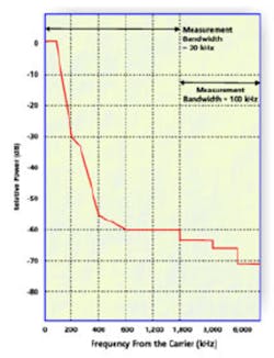
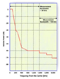
For EDGE, using 3π/8 8PSK modulation, relative power must be -30 dB as measured in a 30-kHz bandwidth offset 200 kHz from the carrier. Figure 1 shows what you typically want to see in a spectrum due to modulation and wideband noise.
Power
Power is the most tested function of the mobile. With an increased number of users in a limited spectrum chewing away at network capacity, the power accuracy of the mobile will be watched closely.
Not only do we need to test the power accuracy of the mobile, but we also must check the capability of the phone to quickly change power levels. This usually is done with a power-step test process that looks for accuracy from one power level to the next. In the case of R&D and verification and validation, you also will look at settling time once the mobile attains the new power level. Typically, these tests are done with a power meter or a dedicated radio test system that includes all appropriate signaling for controlling the mobile’s power output and are triggered to correspond to the burst timing.
EDGE adds three new power classes, E1, E2, and E3, to the conventional GSM/GPRS power classes. The maximum output power for 3π/8 8PSK in any one band always is equal to or less than GMSK maximum output power for the same equipment in the same band.
Burst Profile
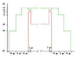
The burst profile of the mobile tells us much about how well the transmitter is performing. Figure 2 shows an EDGE 3π/8 8PSK burst profile. Both the GMSK GSM and GPRS bursts have the same burst profile. EDGE 3π/8 8PSK bursts have the same rise and settling time as GMSK; however, due to the modulation, the power range will vary much more than GMSK modulation. The specification for the lowest end of the profile is -59 dBc or -54 dBm, whichever is greater, and applies to GSM 400, GSM 850, and GSM 900. For the time slot preceding the active slot, the allowed level is -59 dBc or -36 dBm, whichever is greater. For DCS 1800 or PCS 1900 operation, the specification is -48 dBc or -48 dBm, whichever is greater. Burst profiles, since they are time dependent, must be analyzed with a dedicated radio test system or a test system triggered to measure the power over just the time that the slot is active. rms and Peak Phase Error For GMSK modulation, phase error testing checks the modulation accuracy of the transmitter in the mobile under test. It is made on the useful part (information or data) of the burst and usually averaged over a predetermined number of bursts. Peak is the worst-case measurement of the burst phase error.
Frequency Error
This is a test of the stability of the mobile’s transmitter; its ability to keep on frequency regardless of modulation format.
Bit Timing
This test checks the accuracy of the mobile’s transmission timing. To accommodate for the near-far effect, the network can request that the mobile advance its burst by a predetermined number of bits.
EVM
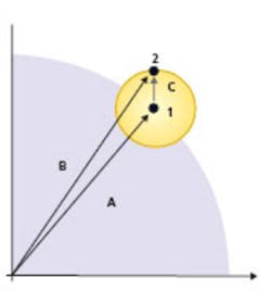
EVM checks the modulation accuracy of the transmitter in the mobile under test. It is derived from the plot of the symbol on an I/Q quadrant map to determine the magnitude of the error vector and is applicable for 3π/8 8PSK modulation associated with channel-coding schemes MCS5—9 for EDGE. Figure 3 shows how EVM is determined. The EVM (Vector C) is measured from the ideal point (1) to the actual landing point (2) of the symbol.
Phase error, frequency error, bit timing, and EVM must be tested with specialized systems that take into account phase transitions associated with digital modulation schemes. Regular frequency counters cannot render accurate measurements because of the phase variations. DSPs in newer radio test systems backwards calculate frequency, timing, and EVM based on an ideal waveform reference that, in reality, never is produced by the mobile.Receiver Tests
Receiver tests determine the sensitivity of the receiver or how low a signal the mobile can process before it causes excessive errors. In analog days, this was a SINAD test. For digital modulation techniques, however, we need to look at something called BER.
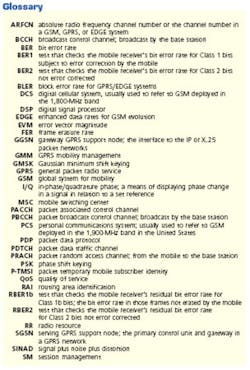
For GSM, many BER tests depend on the class of bits that the mobile processes. There are four BER tests associated with GSM (BER1, BER2, RBER1b, and RBER2) and another test called FER, which measures complete frames of data that are lost. GPRS and EDGE add another test for receiver sensitivity called BLER. Blocks in a packet data environment consist of four consecutive bursts. The BLER is the ratio of improperly received blocks to the number of blocks transmitted.BER, FER, and BLER must be tested to a particular standard by sending either a random or a predetermined number of bits to the mobile. The results then are monitored by either tracking the mobile’s reported error rates or, through a method called a loop-back test, the actual number of errors vs. a known stream of data. Typically, these tests are performed using radio test systems that provide the proper signaling and bit-stream analysis.
Protocol Tests
Digital wireless communications rely on messaging in the form of signaling data. With any cellular system, a control channel and a traffic channel exist. The control channel is different from the traffic channel because it acts like a beacon from a lighthouse that the mobile can see, and it provides information about the network to the mobile. It also controls various assignments to the mobile for slot assignment, ARFCN, and other functions. Once the mobile gathers information about the system and the network knows the intent of the mobile, it transfers the call to a traffic channel for the call to take place.
When a GPRS or EDGE mobile initiates a data call, it first finds a BCCH or PBCCH that meets its parameters for accessing the network. After finding the appropriate network, it sends a PRACH using an abbreviated burst to the base station. The base station then initiates a GPRS attach session that establishes the protocol for that session based on the QoS requirements and the network’s and mobile’s capabilities. After the mobile has the parameters set for a data call, the network instructs it to go to a PDTCH where the data session is executed. Further control of the mobile from the network is accomplished using a logical control channel called a PACCH.
Logical channels are channels mapped onto the physical channels and contain the various signaling needed to process a data call. These logical channels include the data we are sending and the underlying signaling used to control the call.
In a GPRS/EDGE system, logical channels control the function of the radio in concert with the network. These functions can be broken down into RR, GMM, and SM.
RR deals with the RF transmission parameters. Power, frequency, bit timing, channel-coding schemes, hand-overs, and slot control are controlled by logical messages over a number of sequential bursts. These bits of information initially are sent on the BCCH or PBCCH then transferred to the PACCH while the mobile is receiving data on a PDTCH. RR deals with the various resources needed to maintain the call.
GMM deals with the capability of the mobile unit to roam across networks. In GRPS and EDGE systems, mobility management is handled through the SGSN rather than the MSC associated with GSM. Mobility management also includes the assignment of the P-TMSI and control of the RAI. The GPRS attach process also is controlled by mobility management.
SM handles the transfer of application data to and from a mobile unit. It includes the handshaking procedures and the establishment of the PDP context between the mobile and the GGSN for QoS profiles and PDP addresses.
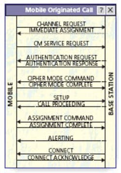
The whole goal with protocol signaling is to ensure that the payload (data) gets where it is supposed to go by taking into account all the variables that a GPRS or EDGE mobile phone can encounter in a mobile environment. Test systems use various means to depict and control the messaging going back and forth between the mobile and the base station.
The most common means uses message sequence charting. Figure 4 shows how a message sequence chart can track the various messages transferred between the mobile and the network.Protocol support in test equipment can vary based on the application. Some test systems provide just the basic signaling for establishing a call so then you can perform parametric measurements for manufacturing and service applications. Some test systems have full-blown conformance systems that test almost every aspect of the signaling for use in R&D and verification and validation of the mobile.
As technology becomes more and more complex, the test-equipment manufacturer must supply highly accurate and flexible platforms that provide parametric measurements. These platforms must have the capability to define specific signaling for testing how well the mobile will perform in a constantly changing environment.
Reference
Siegmund, R., Weber, M., and Oliphant, M., An Introduction to GSM, 1995.
About the Author
Rob Barden is senior product marketing manager at IFR Systems. He has been in the test-equipment industry for more than 16 years and with IFR for the last three years. IFR Systems, 10200 W. York St., Wichita, KS 67215, 316- 522-4981, www.ifrsys.com For More Information For more information on this topic, visit our website at www.evaluationengineering.com and access the Article Archives.
April 2002
