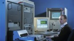
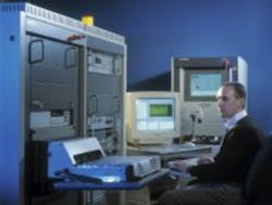
The repetitive nature of power supply test and the need for accuracy, repeatability, and documentation make it a prime candidate for automation. Today’s leading-edge power supply test systems offer much more than mechanization of a manual process. Sophisticated software techniques are being applied throughout the product life cycle to add value to the design, production, and repair processes.
Design Characterization
Virtual Instrument Control
Traditionally, the inherent requirement for flexibility in characterization has meant that, where other types of testing have become increasingly automated, characterization testing remains a manual task.
Now, by making use of the latest developments in instrumentation control software, many power supply automatic test equipment (ATE) manufacturers are offering systems that automate the repetitive stimulate-measure-document tasks of characterization. Using virtual instrument control, these systems give the engineer complete flexibility to create and control tests as before but with the added system intelligence that can store and repeat test procedures, automate settings and measurements, and log results.
For example, consider ripple-testing a power supply unit with 10 outputs. Each output must be loaded incrementally from minimum to maximum and the ripple checked at each step on each output. Also, since ripple is a function of loading, the limits have to be recalculated for each measurement. Carried out manually, it is repetitive and time-consuming, and the possibility for error in setting up the test and documenting the results is high.
Transfer this operation to an automated system, and the time savings are significant. The time required for characterization is reduced from days or weeks to literally hours of work, and the possibility for error is greatly reduced. Instead of a clutter of benchtop instruments and wires, the engineer now works with a single rack of instrumentation, all controlled directly from a PC. Data is logged and analyzed and reports generated automatically.
As a result, engineers can evaluate their designs much more closely than before, leading to better designs and a reduction in the engineering time spent generating reports.
Conformance Test
In addition to ensuring that the product meets all its functional specifications and life-cycle specifications, it is becoming increasingly necessary to perform once-off conformance testing on each new design. Conformance to internationally applied standards governing electromagnetic compatibility of the products and power-quality performance are required when selling into worldwide markets. This often necessitates the use of specific equipment such as spectrum analyzers and EMC generators that further underlines the importance of having an open test executive capable of integrating new instruments and generating different test strategies.
Production Test
The primary driver today in production test is speed. It is no good optimizing your manufacturing processes only to find production bottlenecks in test. Increasing test productivity without sacrificing accuracy, reliability, and repeatability has been a key issue for the industry.
The overall efficiency of the production test process is defined by the test time, the time required for handling each power supply unit, and the efficiency with which the results are logged, analyzed, and presented.
Test Time
Research by Schaffner has identified the two factors key to reducing test times as the duplication of measurements in the test program and the minimization of power supply settling times.
Traditionally, ATE software allowed you to set up a sequence of tests that was saved into a test program. When the program was executed, the software implemented each test in turn by allowing the unit to settle to the appropriate level, taking the required measurements, and logging the results.
Now, the fastest ATE uses a test methodology that eliminates this duplication of measurement using a series of tests to measure and store all the values required for the test program. Each measurement is performed only once, and the power supply unit passes through each state change only once. The measured values then are made available to a series of evaluation tests that calculates the required results such as output voltage, load regulation, line regulation, and efficiency.
As an example of the test time savings achievable with this approach, consider a line regulation test on a DC-DC converter power supply with multiple outputs. Under the traditional approach, each set of measurements would have to be made for each output at line-high (maximum input voltage) and line-low (minimum input voltage) settings.
Using the new concept, the low-line level is set and the output voltages measured, then the high-line level is set and the outputs measured again. If the source settling time is 20 ms, the power supply settling time 25 ms, and the measurement time 20 ms, then for a five-output power supply, the time to carry out the line regulation test reduces from 650 ms to 290 ms by using this method. This is a test time savings of more than 40%. Further, the time allowed for settling is reduced to its practical limit for each measurement.
Traditionally, ATE software allowed a predefined, fixed amount of time for the power supply to settle following a state change before making a measurement. The settling times were based on experience and gave a sensible margin.
The new concept uses a programming loop to verify the actual state of the power supply. As soon as the unit is sufficiently settled to allow the measurement to be made with statistical certainty, according to the required resolution, the measurement is implemented. This reduces the time allowed in the test for settling to its practical minimum.
Recent Developments
As test times decrease, the time required for handling and loading boards is becoming critical to throughput in some test installations. Manufacturers are increasingly considering the use of automated handling systems, electronic bar-code readers, radio-frequency identification (RFID) tags, and multiwell fixtures to maximize throughput.
Intelligent Test
At the other end of the process, faster delivery of test results and the ease with which the data can be accessed and used also are issues. Open-architecture, network-friendly systems can be configured to deliver test data directly to a central server or an intranet for access by design or management personnel, colleagues at other sites, and field-repair engineers.
Some manufacturers go further by implementing a fully automated, networked intelligent factory. For this concept, each manufacturing stage communicates with and is controlled by a central server that tracks the progress of each unit through the production process.
Batch and specification information is logged along with manufacturing data and test results. The server collates the data with test and manufacturing data of the other units in the batch, carries out statistical analysis, creates a series of graphs, and posts the reports on the engineering intranet for access by the design team.
One recent example of the practical application of intelligent testing is given by a Schaffner customer who makes a chassis-based power supply with 10 outputs. A range of plug-in submodules is available, and customers can specify the configurations.
The large number of configurations possible and the fact that units often can be ordered in relatively small numbers present a problem for production test. Creating a complete test program for every possible configuration would be very time-consuming and, since some configurations may never be requested, would not be an efficient use of programming time.
The solution is an intelligent test system that recognizes the configuration of the unit under test, works out which measurements need to be made, then carries out the test accordingly. In this way, the system can handle every possible configuration of a power supply, and test-programming overhead is minimized.
In another example, the need for visual inspection of LEDs on a power supply was met by integrating a video camera into the system. Similarly, thermal-imaging systems can be used to check for hot spots. Once the principle of built-in networked communications with open-architecture software is accepted, the possibilities to add value to the test process by integrating third-party equipment or applications are practically unlimited.
Reliability Stress Screening
For many manufacturers, reliability stress screening (RSS), often referred to as burn-in, is an expensive chore. Traditional methods require the outputs of the power supply to be connected to a conventional resistive load for an extended period of time; 12 or 24 hours are typical. The energy is dissipated as heat, and expensive water-cooling and air-conditioning systems usually are required.
The biggest advance in this area in recent years has been the introduction of green loads for burn-in that recycle up to 85% of power, cutting the large energy bills normally associated with these tests and often negating the need for expensive cooling systems. One manufacturer of 25-kW AC/DC converters for medical equipment saved more than £16,000 ($22,000) annually in energy bills alone by switching to green loads for burn-in test.
Repair
For the diagnostic work required for repair, the issues are similar to those affecting characterization. Virtual instrument control techniques, failure-specific debug tools, and the capability to store test routines help automate detection of the failure. Also, software with powerful structured query language (SQL) features ranging from a fault-diagnostics database to self-learning, neural networks is being used now to carry out diagnostics and repair at the same time.
The Test Platform
The benefits of using the same, open-architecture test platform throughout the design, production, burn-in, and repair cycle now are widely accepted. Test routines created for characterization can be borrowed and simplified for production test and re-used in diagnostics for repair. Communicating data from one section to another—usually back to the design engineering team—is simplified, and consistency in reports is easy to achieve.
ATE Software Developments
For example, many manufacturers with multiple compatible, open-architecture test systems throughout their processes now store test programs in one central database on the network. The latest version of the appropriate test program is downloaded to the tester at power-up, when a new fixture is installed, or when the unit to be tested has been identified by its RFID tag or bar code.
Software upgrades also can be applied automatically to all the testers on the network. In this way, only the correct version of the application and the test program is used, without checking each machine.
Hardware Developments
A wide range of OEM instruments—oscilloscopes, DC supplies, AC sources, power analyzers, DVMs—can be integrated into the ATE hardware according to the exact requirements of the system. Essential to any power supply test system is an efficient way of powering up the unit under test to simulate real-world conditions accurately.
The AC source must provide solid-state frequency programmability for simulation of different utility grids. The trend is to move away from traditional transformer coupling so that one source provides both AC and DC inputs to the UUT.
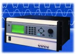
Some of these latest-generation sources simulate the most demanding real-world power conditions. For example, in Schaffner’s 6500 and Intepro 9000 range of power supply ATE, the SmartWave Series of AC Sources from Elgar provides a range of complex features (Figure 1). Three arbitrary waveform generators enable the test system to generate complex waveforms on all three phases simultaneously. AC outputs from 0 V to 312 V rms simulate the majority of the world’s facility power grids, and the slew rate for voltage transitions, typically 20 µs, contributes to test efficiency, especially in high-volume production applications.
The remote-sense capability allows the power source to compensate for any voltage drop across the cables connected to the power supply under test. During the test sequence, as input voltages and frequencies change rapidly, a digital pulse is synchronized during each change, enabling other equipment, such as an oscilloscope, to be triggered during the transaction to capture the output performance of the supply under test.
About the Authors
Tadhg Ferriter spent five years working as a design engineer after earning a B.E. in electrical engineering from UCC in Ireland. In the 12 years since joining Schaffner in a technical-support role, he has continued to focus on the power supply ATE market and now is Schaffner’s worldwide sales and marketing mana-ger for the ATE Systems product division. Schaffner Ltd, National Technological Park, Castletroy, Limerick, Ireland, 011 353 61 332233, ext. 126, e-mail: [email protected]
Don Novotny is the corporate marketing manager at Elgar. During his five-year career at Elgar, Mr. Novotny has been involved in the definition and introduction of AC power sources, most recently for AC-to-DC converters and avionics testing with the ContinousWave family. He received a B.S. in electrical engineering from the University of Illinois and an M.B.A. from the University of Southern California. Elgar Corp., 9250 Brown Deer Rd., San Diego, CA 92121, 858-678-4425, e-mail: [email protected]
Return to EE Home Page
Published by EE-Evaluation Engineering
All contents © 2001 Nelson Publishing Inc.
No reprint, distribution, or reuse in any medium is permitted
without the express written consent of the publisher.
June 2002


