By design, X-ray systems provide the capability to look inside opaque or solid substances to detect defects. So it seems only appropriate to examine them from the inside out before buying one.
Many of today’s microfocus X-ray system manufacturers offer either open-tube or sealed-tube technologies. A sealed-tube X-ray source generally is a glass tube analogous to a light bulb where the contents of the tube are in a vacuum. An open-tube X-ray source, as its name implies, is open.
Open-tube sources, generally consisting of an all-metal construction, create vacuum by a two-stage pumping process every time the system is switched on from cold. The vacuum is maintained throughout the system via a secondary pumping system. Although open tubes may use either directional or transmission targets, for the purposes of this article, any reference to an open tube is indicative of a transmission target.
To determine which type of system fits your needs, several fundamentals must be considered: detail detectability, tube voltage, geometric magnification, application requirements, cost of ownership, and system price.
Detail Detectability
Detail detectability, also known as feature recognition, can be estimated as approximately half of the X-ray source focal-spot size. In general, most sealed tubes will have larger focal spots than open tubes.
The focal-spot size of microfocus X-ray is a fundamental parameter. One technique used for quantification is lateral resolution or the smallest feature that can be differentiated by the system in a top-down view. The smaller the focal-spot size, the sharper the image at high geometric magnification.
Tube Voltage
Tube-voltage requirements depend on the application. Penetration of the sample or photon attenuation is based on three factors: material thickness, density, and mass. The higher the voltage, the greater the penetration capability of an X-ray source.
Voltages for sealed tubes generally range from 80 kV to 150 kV; open-tube systems vary from 100 kV to 225 kV. Both technologies usually have variable voltage ranges starting around 10 kV with increases in increments as low as 1 kV up to the maximum tube voltage.
Tube Current
Tube current controls the quantity of X-ray photons that the tube generates (flux). The end effect of higher current is higher contrast due to less noise. Since the focal-spot size is directly proportional to the power (voltage × current), the tube current typically is smaller at a higher tube voltage to maintain image sharpness. Low-density applications typically require higher current and lower voltage.
Geometric and Total Magnification
Beware of randomly spoken magnification values. The distinction between geometric vs. total magnification capabilities is essential. Geometric magnification is the true or actual magnification without enhancing capabilities, including optical and digital zoom, pixel, and software. Total magnification is the geometric magnification plus the magnification enhancement tools such as zooming and takes into account the optical characteristics of the detector and size of the display monitor.
The larger the geometric magnification, the smaller the observed feature can be and is defined as:
Mgeo = FID/FOD
where: FID = focus-to-intensifier distance
FOD = focus-to-object distance
Open tubes have a minimal focus-to-object distance and are best suited for applications demanding high magnification. Sealed tubes have a larger minimum FOD resulting in lower achievable geometric magnifications.
Open-Tube Technology
Now let’s get into some specifics of open-tube technology and what they have to offer. As an end user, you want tube stability, ease of filament changes, and field serviceability.
Both integrated and nonintegrated open-tube systems are available. In most cases, the X-ray tubes in nonintegrated systems have been designed with stability in mind. These tubes, manufactured with superior internal surface finish and mechanical tolerances, maintain the tube and the high-voltage generator as two separate, nonintegrated entities. This configuration enables full field serviceability of the system.
Integrated systems, rather than addressing tube technology and design, have addressed stability and cost factors by tying together the tube and high-voltage generator, eliminating the high-tension cable. Analogous to a hermetic assembly, integrated systems are not as field serviceable because many parts cannot be replaced individually.
Filament changes will be necessary with open-tube systems. It is important to understand what a filament change procedure entails for the various tube designs on the market, how long it will take to accomplish, and what the resulting effect is on your image quality.
Filament changes of many open-tube systems require mechanical adjustment of the filament and extensive recalibration after filament replacement. This can be a difficult and time-consuming process, and the image quality will depend on how precisely these manual adjustments have been made. The steps can vary, including physically aligning the filament for centralization and height, manually aligning the transmission target and electron gun, and fine-tuning the total alignment.
The most advanced systems offer a plug-and-play filament change process where no mechanical adjustments are needed. These filaments come prealigned, and all adjustments are performed automatically and electronically by the X-ray system. Any user can change the filament. The entire process takes a few minutes and maintains optimal image quality.
The subject of filament changes is a serious concern. It may be helpful during the course of your system evaluations to ask for a written procedure on filament changes.
Application Requirements
A quality sealed-tube system is of great value for many applications. These systems, many capable of 70× geometric magnification, can inspect various components. For example, sealed-tube systems with penetration requirements up to 150 kV and a tube output power up to 10 W yielding current up to 250 µA are not only popular but also excellent tools for BGA inspection (Table 1, see below).
Table 1. Comparison of Sealed-Tube and Open-Tube Systems
Factor
(µm)
Voltage (kV)
Open-tube systems provide a more complete package, yielding a higher level of BGA analysis capabilities. For example, in addition to the higher level of BGA analysis, open-tube systems permit analysis of flip-chip bumps, package inspection, and a wider range of failure analysis in general. These systems accommodate applications requiring higher geometric magnifications, voltage, and tube current.
Open-tube systems are more powerful than sealed tubes yet can be even easier to use with a properly designed control system. With a sealed tube, you basically will have the ability to see the hair on a cricket’s leg. With an open-tube system, you can see if the hair on the cricket’s leg has split ends.
Cost of Ownership and System Price
The up-front costs of open-tube systems generally are higher due to the added support systems such as the vacuum pumps and a more complex X-ray control. However, both technologies have their associated costs.
All major components of open tubes may be exchanged, resulting in a virtually unlimited tube life. Open-tube systems require a scheduled maintenance program and have consumables such as filaments, targets, and seals. Sealed-tube systems require minimal maintenance with the tube itself as the only consumable. Typically, sealed-tube systems have a life span of three to five years depending on usage and design.
The Image Chain
The detector is the next important piece of the X-ray system. Like the X-ray tube, detectors come in different flavors and are broken down into two categories: analog or digital.
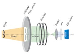
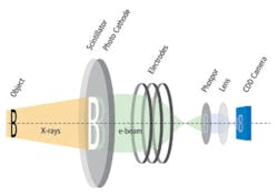
The most popular and economical analog image acquisition method is the X-ray image-intensifier device coupled with a high-resolution CCD camera. The image intensifier is an analog device contained in a large evacuated glass envelope. It comprises a scintillation screen and a photo cathode by which the X-rays are converted back to electrons, then accelerated to produce a smaller, brighter image on a second, phosphorescent screen similar in operation to a CRT (Figure 1, see below).
The output from the image intensifier enters a chain consisting of lenses, a CCD camera, the image processing system, and the final output onto a monitor. Many manufacturers use general-purpose cameras that, although relatively inexpensive, do not offer the best contrast.
A small handful of manufacturers uses cameras that are sensitive to the spectrum of light emitted by the intensifier. These optimized cameras usually are identifiable by their pancake or disk-like design.
Image-intensifier packages are offered with 9″, 6″, and 4″ input areas. Image intensifiers also are available with combination modes such as dual-field (6″/4″ or 4″/2″) and trifield units (9″/6″/4″).
The magnification factor and image resolution will vary with intensifier selection. The X-ray-to-light conversion efficiency increases with the diameter of the input field. A smaller intensifier will provide higher magnification but requires more flux.
The digital or flat-panel detectors come in various configurations, such as a solid-state amorphous silicon sensor operating as a two-dimensional photodiode array. X-rays are converted to light using a vertical structured scintillator. The flat-panel detector consists of a photo-diode matrix and a scintillator screen for X-ray conversion.
The amorphous silicon-based digital detectors provide up to 16-b, 64k gray-scale images as compared to 8-b, 256 shades of gray provided by the camera of an image-intensifier system. The digital detector, with its higher cost, is useful for capturing small changes in material density and examining low absorbing materials such as nonconductive epoxy. Some cameras can be upgraded from 8-b, 256 gray scales to 10 b or 12 b, providing some improvement.
Manipulation
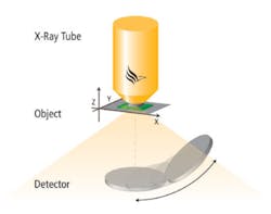
Some open-tube systems have a wide irradiation angle of approximately 170º that offers oblique views at highest magnification (OVHM) and up to 62° as an option (Figure 2, see below). Sealed-tube systems apply tilt-axis capability to obtain angled views. OVHM is not an option for sealed tubes due to a much narrower irradiation angle.
Oblique views at high magnification are obtained by moving the image intensifier and capturing the X-rays at the angle requested. An arc-intensifier movement prevents image distortion since the detector always is pointed at the focal spot. As a result, the sample does not need to be tilted, and the feature of interest can be kept as close as possible to the focal spot.
Unlike the tilt technique, there is minimal loss of magnification in the oblique view. Depending on the configuration, some systems lose magnification or scan area as the tilt angle increases. Isometric centering is essential when using oblique-views because it maintains the centered object of interest in view at any angle, horizontal rotation, or magnification.
Two distinguishing differences of oblique-view configurations are based on placement of the tube and the image intensifier within the system:
Configuration A
To capture the image, the X-ray source is pointed down through the sample, the table, and finally to the image intensifier located at the bottom of the system. In most cases, these systems use an anticollision system (ACS), making collision between samples and the X-ray tube impossible.
A password-protect capability should be provided with ACS systems so only a qualified engineer logged in the administrator mode can disable it. This configuration allows for continual X/Y manipulation from a high-precision horizontal stage with a proportional joystick.
Configuration B
The X-ray source is pointed up from the bottom of the system through the table and the sample with the image intensifier located at the top of the system capturing the image. To obtain maximum magnification in this configuration, the sample table must be removed and the sample placed directly on the tube head. Without any manipulating device between the sample and the tube, X/Y manipulations must be done by hand. Manipulating the sample while running live, real-time X-ray is impossible.
Manipulation Configurations
Some sealed- and open-tube systems can offer up to seven axis manipulation capabilities. Systems with stationary tube configurations manipulate views using the table (rotation, X, Y, and Z) or the image intensifier. A stationary tube maintains a constant X-ray flux as the magnification is adjusted.
A moving tube changes magnification when the relationship changes between the FOD and FID. This results in flux level changes at the detector.
The X-ray flux decreases with lower magnification and increases with higher magnification. While this can be somewhat compensated for with the automatic gain control of the camera, measurement repeatability is reduced. A fixed X-ray tube will provide a constant X-ray flux and better repeatability.
Manipulator motor types include stepper and DC servo. Systems equipped with a stepper motor with an optical encoder system eliminate drift and hunting potential. A stepper motor also reduces equipment size and heat and does not require frequent recalibration. DC servo motor/optical encoder systems driven by analog servo amplifiers tend to generate excessive heat and noise and may require frequent recalibration of the servo amplifiers to reduce wobble or drift.
Software
Programming capabilities and a user-friendly graphical user interface (GUI) are key. Having the tools is great, but being able to use them is essential. Image processing and filtering functions that provide comprehensive capabilities for custom and standard applications plus a user-friendly GUI are necessary.
Programming can be accomplished in minimal time. Programming capabilities automate manipulation, X-ray parameter control, and image processing in conjunction with embedded software for specific applications analysis, such as automatic BGA inspection (Figure 3).
Selecting a System
Maximize the dollars allotted for your system. Ultimately, the system you select must be appropriate for your current as well as future applications. It also must accommodate the changes in production to smaller, denser materials to reflect today’s technology trend. The maximum value for the dollar is not the least expensive system out there, but the best system for the money.
Contact X-ray vendors that can provide you with a solution within your budgetary constraints. Since image quality is essential, submit samples of your product to each of the qualified vendors for imaging.
After determining which systems provide the best quality, go step by step through the features, further narrowing down the list. Then, request a hands-on demonstration of each potential supplier’s recommended configurations. Driving a system yourself will tell how well a system is going to fit your application and facility needs.
About the Authors
Ilene Currier is the East Coast sales engineer for phoenix|x-ray Systems + Services. She has 15 years of experience including R&D of chemistries for the PCB industry and technical field service and technical sales for the PCB assembly industry. 805-444-7436,
e-mail: [email protected]
Jay Adams is the West Coast sales/applications engineer at phoenix|x-ray Systems + Services. He has been with the company for three years and active in X-ray test since 1996. 805-389-0911, e-mail: [email protected]
phoenix|x-ray Systems + Services, 3883 Via Pescador, Unit A, Camarillo, CA 93012
FOR MORE INFORMATION
on microfocus X-ray inspection
www.rsleads.com/307ee-179
Return to EE Home Page
Published by EE-Evaluation Engineering
All contents © 2003 Nelson Publishing Inc.
No reprint, distribution, or reuse in any medium is permitted
without the express written consent of the publisher.
July 2003


