Cars with FlexRay networks are definitely worth waiting for.
You may have seen a recent commercial showing a car automatically correcting itself to prevent a rollover accident or perhaps a vehicle automatically braking to prevent a rear-end collision with the car in front of it. In recent years, the amount of electronics used in automobiles has increased significantly. This trend is expected to continue as automobile manufacturers initiate further advances in safety, reliability, and comfort.
The introduction of advanced control systems, which combine multiple sensors, actuators, and electronic control units (ECU), has begun to place boundary demands on the existing Controller Area Network (CAN) communications bus found in most of today�s automobiles. As a result, initiatives by automobile manufacturers and suppliers have led to the creation of FlexRay, an open standard for a new deterministic, fault-tolerant, and high-speed bus system.
Today, CAN is used in the automotive industry as the primary in-vehicle network for enabling any device to communicate and work with any other device on the network without creating a great strain on the bus. This communication is ideal for powertrain and body electronic applications, such as acceleration skid control (ASC), which requires communications between multiple devices including engine timing and carburetor control units to reduce torque when drive- wheel slippage occurs.
Another use for the CAN network is on a vehicle�s instrument panel, which typically consists of a speedometer, a tachometer, and fuel and temperature gauges and is updated with data that travels from the actual sensors to the dashboard through the CAN network. In addition, the CAN network can increase passenger comfort in vehicles. Examples of this include air-conditioning, lighting, and side-mirror control.
In addition to CAN networks, many vehicles use additional buses for smaller subnetworks within the vehicle. For instance, J1850 and Local Interconnect Network (LIN) connect the many devices present within a single device, such as a passenger seat. Media-Orientated Systems Transport (MOST), as the name implies, is a common bus used for multimedia networking of devices such as DVD players with the many different speakers in the vehicle. These subnetworks are all connected to each other by gateways that allow them to connect to the main CAN network as a single device.
As electronics continue to spread into virtually every aspect of cars and driving, in-vehicle networks will need to expand their functionality. Future in-car control applications, such as drive-by-wire and brake-by-wire, will replace direct mechanical control of a vehicle with ECU-generated bus commands. These new application areas require features that existing communications buses simply cannot address.
For instance, safety-relevant applications have absolute real-time requirements. Put another way, a high-priority message must be transmitted in a predefined amount of time. As you can imagine, when braking, it is absolutely essential that the correct data be sent from the brake pedal to the actual brakes without any unpredictable latency in the communications.
These safety-relevant applications also require increased levels of tolerance against faulty components within the entire system. Using the same example, if one of the wires of the communications bus were to break or loosen, it would be essential for the data to have another route to reach its target. The increase in the shear number of electrical devices in vehicles also will require a higher bandwidth to handle the increased volume of data being sent across the communications bus.
The data transfer rate is another area where today�s communications buses will be insufficient. In the future, powertrain applications will require data to be sent between devices at rates far exceeding the 1-Mb/s limit available on today�s networks.
Realizing that today�s communications buses would not be able to meet the demands of tomorrow�s in-vehicle network applications, BMW and DaimlerChrysler combined forces with Philips and Motorola Semiconductor Product Sector (now Freescale) to form the FlexRay Consortium in 2000. The consortium now includes some of the automotive industry�s largest and most influential companies such as General Motors, Ford, and Bosch.
The consortium is an alliance of more than 100 members composed of automobile manufacturers, systems suppliers for the automotive industry, semiconductor manufacturers, and experts in communications technology systems. The focus of this collaborative group is a new standard that will meet and exceed future requirements for a deterministic and fault-tolerant bus system with high data rates for advanced automotive control applications. The consortium finalized the FlexRay Communications System Specifications Version 2.0 in the summer of 2004 and has since made them available to the general public.
Data Transmission and Topology
A very important requirement is the increase of the maximum data transmission rate up to 10 Mb/s or even more. FlexRay supports a transmission rate of up to 10 Mb/s.
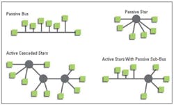
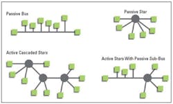
The topology of a FlexRay network can be designed in many ways, such as passive bus, passive star, active cascaded stars, or even active stars with added passive sub-buses (Figure 1). These design alternatives offer important features for in-vehicle network designs like topology scalability and fault-tolerance support.
Failure Tolerance
A failure-tolerant system must ensure that no participant blocks the communications system. The effect of a physical error on the network, such as a short circuit, can be reduced by shutting down the affected network branch. The failure containment in the time domain has to be controlled by an independent instance. FlexRay offers an optional watchdog, the Bus Guardian, which isolates the communications controller from the network on demand.
Deterministic Communications
Today�s in-vehicle network systems exchange information in an asynchronous cyclic or noncyclic manner where all existing communications protocols are event based. As the amount of data on the bus increases, the determinism and worst-case response of the network decrease dramatically.
In time-triggered network systems like FlexRay, however, any network activity is launched in predefined time slots and cannot be changed after launching the cluster. As a result, the FlexRay network can never have an overload of bus traffic.
Time Synchronization
A FlexRay system adjusts the local time of an electrical control unit with the help of special control algorithms. This ensures that all of the local clocks of the individual nodes in a cluster are running synchronous to a global clock. Offset correction and time correction are the two methods used to achieve this global time synchronization.
Configurable Synchronous and Asynchronous Transmission
The communications cycle is the fundamental element of the media access scheme within FlexRay. The time window, defined by the communications cycle, is composed of a mandatory static segment and an optional dynamic segment. The length of each of these segments is defined and fixed during the network configuration.
The static segment of the communications cycle is used for scheduling time-triggered messages and reserved for synchronous communications, which guarantees a specified frame latency and jitter through fault-tolerant clock synchronization. The messages transferred in the static segment must be configured before starting communications, and the maximum amount of data transferred cannot exceed the length of the static segment.
The dynamic segment of the communications cycle is used for event-based messages that may emerge at run time and require varying bandwidths. Within the dynamic segment, devices compete for bandwidth using a priority-driven scheme that assigns priority based on a message�s Frame ID. This part of the cycle forms a communications scheme similar to the CAN bus.
In Figure 2, the communications cycle is shown over a given time period. It illustrates that the bandwidth used for time-triggered and event-triggered messages is scalable.
Frame Format
An overview of the FlexRay frame format is illustrated in Figure 3. The FlexRay frame divides into three segments: Header, Payload, and Trailer.
Figure 3. FlexRay Frame Format
Header
The Header includes the Frame ID, Payload Length, Header CRC, and Cycle Count. The Frame ID identifies a frame and is used for prioritizing event-triggered frames. The Payload Length contains the number of words that is transferred in the frame. The Header CRC detects errors during the transfer. The Cycle Count contains the value of a counter incremented each time a communications cycle starts.
Payload
The Payload has the data transferred by the frame. The length of the FlexRay payload can be up to 127 words (254 B), more than a 30� increase compared to CAN.
Trailer
The Trailer has three 8-b CRCs to detect errors.
Although the FlexRay protocol only recently was made available to the general public, it already has begun to establish itself as the de facto standard for future in-vehicle networks. FlexRay products and tools already have been introduced to the automotive industry.
Freescale Semiconductor was the first company to bring FlexRay silicon to market. The company�s background in communications technology and work with earlier innovative high-speed vehicle networks such as byteflight have enabled Freescale to deploy FlexRay controller implementations since 2002.
Freescale�s MFR4200 FlexRay Controller is in production now, and vehicles using FlexRay are expected to enter the market in 2006. Freescale is developing PowerPC and S12 integrated MCU solutions for powertrain, body and chassis, and by-wire applications, which are expected to be available by late 2005.
Scheduling Tools
Complex network systems such as FlexRay require tools that focus on the application the engineer has to solve rather than on the network design process or the access of network information.
The first step in creating a FlexRay cluster, a communications system of multiple nodes directly connected via at least one communications channel, is to design the participants of the network and their function model. Several design and scheduling tools are available; however, only a few of them offer a user-friendly interface to configure nodes and scheduling information. These tools are used to create controller host interface (CHI) configuration files that must be uploaded onto the FlexRay controller before the nodes in the cluster can be launched.
One example of a scheduling tool is the FlexConfig software package from TZ-Mikroelektronik (TZM), a universal configuration tool for FlexRay networks. Until recently, many application engineers configured FlexRay controllers by working with stacks of specification papers. This process is greatly improved using FlexConfig because all necessary parameters are set by the user via a Windows application.
Almost every parameter is checked against general limits or specific constraints to minimize faulty configurations. FlexConfig enables the user to generate all configuration sets for each cluster node out of one project. These sets also can include node-specific buffer settings.
FlexRay Bus Analyzing
The FlexCard� offered by TZM is a plug-in interface for laptops and desktop computers with PCMCIA connectivity and can be used for network monitoring purposes. With its functionality, the FlexCard allows hardware developers to interface with the FlexRay network. To prevent data loss during temporary blocking of the bus connection on the PC side, a 16-MB buffer is provided which temporarily stores incoming data.
Moreover, the physical layers for the two channels are integrated into the card. This is a significant advantage because the relatively high number of conductors to the physical layer (Bus Driver and Bus Guardian) does not have to be led outward so the interference liability is drastically reduced.
The physical layer is situated in the extension pack, a physical extension of the card. The user can choose here to operate with the RS-485 bus drivers or to communicate via the FlexRay Physical Layer modules. The update capability to new physical layer chips is not restricted since they are situated on a separate board within the FlexCard housing.
FlexRay Library for LabVIEW
National Instruments recently introduced a LabVIEW programming tool for the FlexRay bus: the FlexRay library for LabVIEW to test devices on a FlexRay communications network. The free, downloadable FlexRay library offers a set of 28 virtual instrument (VI) function blocks designed to work with the bus protocol defined by the FlexRay Consortium.
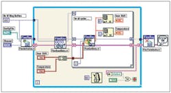
The general programming flow for most FlexRay applications consists of four sub-VIs. The FlexInitialize.vi opens, configures, and starts a single FlexRay channel. The FlexReadData.vi reads bus data from a FlexRay channel and writes it to an internal read buffer. The FlexGetData.vi checks the internal read buffer for data and converts the data to floating-point values. As a result, the VI returns these floating-point values. The FlexTerminate.vi stops and closes communications to a single FlexRay channel.
Figure 4 illustrates the basic FlexRay programming model using some of the VIs in the FlexRay library for LabVIEW.
Summary
Although cars with FlexRay networks won�t appear in auto dealer showrooms until 2006, these vehicles will be worth waiting for. FlexRay leapfrogs present CAN capabilities by supporting a 10-Mb/s data rate and both synchronous and asynchronous data transmissions. Most importantly, the system is failure tolerant and provides deterministic data transfer, two factors essential to the safety of future brake-by-wire and steer-by-wire applications.
The transmission protocol is based on preallocated time slots so no arbitration is required. This and characteristics such as a wide variety of supported topologies, fast error detection, flexible bandwidth allocation among nodes, and the optional Bus Guardian bus monitor make for efficient operation. Equally critical to the successful adoption of FlexRay has been the availability of flexible development tools and production-quality silicon.
About the Author
Joel Shapiro is the industrial communications product manager at National Instruments. He joined the company in 2002 as a member of the Engineering Leadership Program and spent a year as a team manager in the Applications Engineering department. Mr. Shapiro graduated from the University of Tennessee with a B.A. in computer science. National Instruments, 11500 Mopac Expressway, Austin, TX 78759, 512-683-8378, e-mail: [email protected]
FOR MORE INFORMATION
on the FlexRay Automotive Communications Bus
www.rsleads.com/503ee-214
March 2005


