Proper selection and effective testing can increase contact reliability in the end product while reducing the overall cost of using relays.
Who said relays are pass�? While electromechanical relays have been switching electrical signals for more than 150 years, they continue to be the switch of choice for many applications.
One primary application is in ATE where sensitive measurements are required over an array of multiplexed signals. An electromechanical relay offers practically zero closed impedance (100 G?) while providing high bandwidth characteristics of greater than 100 MHz.
However, this remarkable device can become the Achilles heel of very expensive ATE if not properly selected for the application. A single ATE can use thousands of relays, and poor relay reliability can translate into serious downtime and expensive field repairs.
Quality vs. Reliability
Many component users compare the reject rates of two suppliers and assume that the lot with the highest yield will offer the best performance. The user may be disappointed with the performance of the relay in the end product unless a relationship between quality and reliability has been established for a particular application.
Quality generally is defined as a measure of how well a component complies with a specification before it is installed in the end product. In many cases, this measure of performance against test limits does not consider component life.
Reliability is a measure of component performance during the useful life of the end product. While semiconductor life is a function of time and temperature, relay contact life is measured in terms of contact load and the number of contact operations.
Life testing should be performed during relay qualification to confirm that the contacts satisfy the minimum life value. The relay user should be cautious in accepting published life test data. This data may not be relevant if the life testing was performed at a contact load other than the user�s worst-case load.
Published data may be based on typical rather than minimum life and would not tell the user when to expect the first failure. In addition, the data may be based on a 10% failure rate during the life test although the user requires a failure rate of less than 0.1% in the end product.
Proper Selection
The relay specification should define the requirements of the end application. The operating voltages (turn-on and turn-off) and the timing (close and release times) must be specified with sufficient margin to assure good, reliable performance.
The life expectancy should be defined in terms of relay cycles. This often is difficult to determine since most designers specify the total hours required (MTBF) or the minimum acceptable failure rate (FITS).
Unlike other electrical components, relays do not age until they are actually switched. For that reason, relays are specified in terms of millions of cycles of operation. Encapsulated dry-reed relays typically will operate for hundreds of millions of cycles while the life of armature-type relays generally is an order of magnitude less.
Assessing the application requirements for life is very important. This involves looking at the maximum switching frequency and the total life expectancy of the system. For example, if a relay were switched at just 25 Hz continuously, it would only take 11 hours to reach 1 million cycles, 111 hours for 10 million cycles, and 1,111 hours for 100 million cycles. This part would wear out in only a couple of months in this application. Consequently, even a reed relay should only be used in circuits that will switch at a rate to ensure long life.
Consider an example where the test cycle for an ATE is 10 seconds and the relay is switched one time during each test cycle. It would take four months to reach 1 million cycles, about three years to reach 10 million cycles, and about 30 years to reach 100 million cycles.
This is one reason why properly judging the application is critical to selecting the proper life specification for the relay. The total cycles per year for the relay should be specified well below the requirement to ensure that its failure rate is in the same range as a solid-state device.
Load Effect on Reliability
Another application factor that can greatly reduce the specified life of electromechanical relays is the switched load. The load-carrying capability of the relay often is confused with its capability to switch a particular load repeated times.
The ideal way to switch relays is to first remove the load, operate the switch, and then reapply the load. Voltage levels of 1 to 2 V can be switched without significantly affecting the life of the relay. However, life degradation occurs rapidly when switching 5 V or higher due to arcing at the contacts.
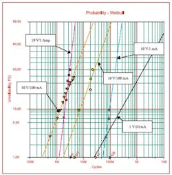
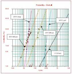
In one study, samples of a reed relay were life tested with loads of 1 V/10 mA, 10 V/1 mA, 10 V/1 A, and 30 V/100 mA. The results from these four life tests are plotted on the Weibull chart in Figure 1, and the effects of switching higher load voltages can be seen.
Current limiting also can be very beneficial to improving the life expectancy for the same load voltage. There is a marked difference for the 10-V load between 1 mA and 1 A. The life test results show the total cycles improved by more than an order of magnitude when the current was limited. It also can be observed that the life expectancy was reduced by two orders of magnitude when the load was increased from 1 V to 30 V.
How to Find the Best Reliability
For applications requiring the absolute highest life from the relay, several methods can improve the statistics after the application has been optimized. Relays that have smooth and well-aligned contacts exhibit the best life characteristics. Good contacts will demonstrate tightly controlled and repeatable contact resistance measurements over many cycles.
One way to identify potential problem parts is to compare the maximum and minimum values of at least 50 contact resistance (CR) measurements. Parts with high differences in this reading have an increased probability of early life failures.
Another method that has been used to determine the integrity of the contact surfaces is called magnetostrictive twist. This phenomenon is unique to dry-reed relays and caused by the magnetic flux of the coil current interacting with the flux of the contact load current. When contacts are held lightly closed, this interaction of fluxes causes the reed-switch blades to twist laterally in relation to each other. Contact resistance measurements made during this test have identified contact surface irregularities that caused eventual contact failure.
In a study, 28 dry-reed relays were life tested for 25 million operations switching a 10-V, 4-mA contact load. There were failures at 8.4M, 12.2M, 21.8M, and 22.6M cycles. Two of the failures were predictable from the initial parametric data. The device that failed at 12.2 million operations had a contact resistance delta (CRdel) value of 5.4 m? (the population mean was 1.0 m? with a sigma of 1.1 m?). The device that failed at 21.8 million cycles had a contact resistance under twist conditions (CRtwist) value 18 m? above the maximum CR reading with nominal coil voltage applied. The mean for this population was 8.4 m? with a sigma of 2.2 m?.
These tests can significantly reduce the overall failures experienced during the life of the part, and a 50% reduction was observed in this study. A parametric test with three sigma limits for Rdel (5 m?) and Rtwist (15 m?) would reject two parts from this population that ultimately experienced early life failures.
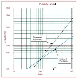
The resulting predicted reliability with and without screening is shown in the Weibull plot in Figure 2. The improvement of the life expectancy at the point where 63% of the population has failed (eta) was 514% (79M cycles to 485M cycles).
click here to see larger image
The second parameter from a two-parameter Weibull distribution is beta. Beta values greater than one indicate wear-out failures while a beta equal to one denotes a constant failure rate. The beta for the unscreened population equaled 1.6; the screened population was 1.
The failure rate for a screened population was approximately 0.2% per million cycles over its life. The unscreened population had an increasing failure rate that ranged from 0.5% per million cycles at the 20 million-cycle point to approximately 0.8% per million cycles at the 50 million-cycle point. The improvement in the failure rate for this study was 150% to 300%.
Conclusion
For electromechanical relays, high reliability can be achieved through a combination of accurately specifying the operating environment, rigorous life testing, and application of special parametric testing tied to the life test results.
Understanding the operating conditions and their effect on the life of the relay is essential to achieving the goals for the expected life in the end system. The number of cycles that the part will be expected to operate over its lifetime and the effect of the load are critical in determining the life expectancy.
For most components, we know there is a relationship between quality and reliability. For relay devices, this relationship often can be defined, and special up-front testing like CRdel and CRtwist can effectively improve field reliability. The impact of field failures is very high when considering the cost of repair, downtime, and customer dissatisfaction.
About the Author
Phil Roettjer is president of Relay Testing Services and has more than 20 years of experience with electromechanical devices. Before joining RTS, he was the director of quality for the Server Products Division at Maxtor. Relay Testing Services, 89 Hartford Ave. East, Mendon, MA 01756, 508-473-5005, e-mail: [email protected]
FOR MORE INFORMATION
on relay reliability testing
www.rsleads.com/504ee-183
April 2005


