Today’s industry trends are prompting semiconductor manufacturers to adopt embedded solutions to compress test time and data volume.
Semiconductor companies on the leading edge of the nanometer migration were the first to experience it�the change, the uncertainty, the risk. They prevailed in finding solutions to both the test quality crisis and the test cost crisis that ensued as a result.
Now this phenomenon is finding its way into the mainstream. Companies are struggling with gaps in test quality as they start testing nanometer designs. And just when they begin to solve the test quality problem by adding new types of test, test cost spirals out of control.
For companies just beginning this journey, it is assuring to know that others have forged their way through these issues. Industry leaders have discovered and proven that new test compression methodologies can solve both the test quality and cost problems.
By compressing test sets, companies can generate and apply more types of tests to ensure higher quality while maintaining or even reducing test cost. However, with the barrage of new solutions available in the market place, how is a company to choose the methodology and tools that will best meet the test needs of its current and future designs?
Test Compression Criteria
When investigating a test compression methodology, look closely at four key areas: test quality, compression results, design impact, and diagnostics. Each of these categories contains a set of criteria that should be well understood and investigated thoroughly.
Test Quality
The reason companies perform tests is to detect defective parts prior to shipping them to customers. Field returns are costly, both in terms of hard cost and company reputation, so test quality should always remain the number-one consideration. To put it simply, it defeats the purpose of test to adopt a test compression methodology that cannot achieve high quality.
Quality is an even greater concern at 130-nm process technologies and below where traditional test, based on the stuck-at fault model, becomes inadequate if not coupled with at-speed test and other new methods. This is due to the plethora of different defects occurring with new materials and smaller process geometries (Figure 1). The population of timing defects has risen dramatically, reducing the effectiveness of traditional stuck-at testing, which never was designed to catch these types of speed-related defects.
When examining the capability of a test solution to deliver high quality, many factors must be considered. First, determine what sort of stuck-at coverage the methodology can achieve. If the coverage is anything less than what automatic test pattern generation (ATPG) offers, it probably is not a good solution for manufacturing test.
Next, consider whether the solution supports thorough at-speed testing. To be considered thorough, the solution should be flexible enough to support path-delay and both broadside and launch-off-shift transition tests. Launching tests from on-chip phase-locked loops also is required to ensure clocking accuracy.
Beyond at-speed testing, the solution should address bridging faults. A deterministic approach can work in concert with design-for-manufacturing tools to intelligently extract the most likely bridges, which then become a target for ATPG. Add a statistical test approach, such as multiple detections, and you can raise the probability of detecting other potential bridges and defects.
When it comes to quality, look under the surface and explore all the options and capabilities. Keep in mind that quality is the most crucial test criteria and that sacrificing quality is a costly action.
Compression Results
After quality, compression results are the next thing to consider. Compression can be measured in terms of test time and test data, both of which directly influence test cost savings.
When companies purchase test time, they typically are charged by the second, so reducing test time can have measurable cost reduction on each part manufactured. If companies own their testers and test times grow 5� to 10�, this increases the number of testers needed to ensure adequate test throughput.
Likewise, test data must be stored on testers. If the data exceeds tester limits, the alternatives�using more expensive testers, adding tester memory, and performing tester reloads�are costly. Always keep in mind, test data compression without test time reduction provides only half the benefit a compression solution must offer.
Not all compression is measured equally. Some solutions make compression claims based on very inefficient ATPG test sets. When you compare solutions, make sure you are doing apples-to-apples comparisons. One way to do this is to measure test data in terms of total bits and test time in terms of total tester cycles.
Additionally, because compression is tightly tied to other test cost initiatives, ensure that the compression solution works with other approaches your company might be investigating. Reduced pin-count test is a common initiative, allowing tests to be run on low-cost testers with very limited pin access. Compression solutions should provide great compression results even under these restrictions to ensure your company is getting the most out of its combined test cost-reduction initiatives.
Design Impact
Schedule slip probably is one of the most frightening occurrences known to project managers and one of the most financially damaging phrases known to executives. It means something went wrong.
Maybe it was due to problems meeting area requirements; maybe it was problems meeting timing. The list of maybes is potentially endless. To reduce this list, it is important to select a compression solution that has minimal impact on the design.
First, understand the impact of the solution on your functional design. Think twice if the solution requires you to modify the functionality of your design to add special test circuitry such as test points or X-bounding logic to achieve high quality or high compression.
Now you have to ask, does my design still meet timing and all the other requirements and expectations? Changing the functional design usually requires complex design flows and additional verification. This spells higher risk. Methodologies that do not interfere with the functional design are preferred.
Second, make sure the solution does not add unacceptable overhead to your design. Any required test circuitry should not only lie outside of your design�s functional logic, but it also should be as small, flexible, and efficient as possible. Additionally, the solution should require minimal top-level pins and not introduce routing congestion.
Third, make sure the solution works on real designs. Sometimes evaluations are done on small or contrived designs simply because there is little time. This could be a huge mistake. Many solutions work fine in the simplest of cases but break down when they encounter the large and complex designs found in the real world.
Put the solution to the test with real designs before you put the company�s dollars on the line. Make sure the solution is flexible enough to allow any number of scan chains or channels for optimal results on different designs. Also, explore whether the compression methodology has any architectural limitations that might impede its capability to work on future designs.
Fourth, make sure you understand the design flow and that the compression solution will support yours. Whether you normally perform test at the end on the full design or block-by-block during the flow, the solution should accommodate your methodology. For example, you do not want to find out in the last days before tape-out that you have routing congestion or X-states that need masking.
Fifth, it�s important that your solution does not lock you into one vendor�s tool flow. For example, if you buy a tool that only works inside a vendor�s synthesis environment and then you move to a new tool in a future design, your compression solution may not work. Tools that are independent of the flow provide greater flexibility.
Last but not least, consider ease of learning, use, and supportability. Some techniques are just inherently easier to adopt and use than others.
Consider how different the compression technique is compared to your current methodology. If it is similar, the transition should be relatively simple. If it requires a great deal of expertise that your team does not currently have, this introduces greater risk to both product and schedule. Also, regardless of what solution you choose, ensure that ongoing enhancements and support will be available in the foreseeable future.
Diagnostics
Ramping yield quickly is one way to increase profit. Even if you meet your design schedule, low yields can put profitability at risk. As a result, fast yield ramp-up is essential, and diagnostics play a key role here. The test compression solution you are investigating should have good diagnostic capabilities.
First, the solution should provide data that is accurate and correlates well with real device defects. Second, the flow should be straightforward, ideally supporting in-production diagnostics directly from the compressed test set. This streamlines the flow as it reduces the need to maintain multiple test-pattern sources. Additionally, directly diagnosing the failure information of the compressed test allows important statistical data to be gathered during production in support of yield analysis.
The diagnostics output should provide as much data as possible to assist failure analysis. Providing layout-based defect information and viewing capabilities is more useful than a list of possible defect locations in the logical netlist. This information can get process engineers one step closer to determining the cause of failures, addressing the issue, and improving yield.
Comparing Compression Architectures and Methodologies
Test compression solutions require both ATPG capabilities via software and compression logic via hardware. First and foremost, ensure the compression tool is built on a state-of-the-art ATPG kernel since this provides a strong foundation for optimal performance and results.
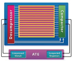
In terms of hardware architectures, all compression schemes use hardware on the design�s inputs and outputs to take compressed data from the tester, expand or decompress it on chip, and then collect response data and compact it to send compressed data back to the tester. At its simplest, every test compression solution requires some form of decompressor on the input side as well as some form of compactor on the output side (Figure 2).
Decompressors
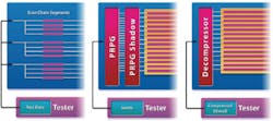
Test compression methodologies typically decompress test data in one of three ways: Illinois scan (scan segment approach), reseeding, and continuous-flow decompressor (Figure 3).
Illinois Scan Reseeding Continuous-Flow
Decompressor
Illinois scan has been around for many years. To achieve decompression, this simplistic approach applies one set of scan data in parallel to a number of scan segments.
This methodology can achieve ATPG-like quality for simple types of tests. But the more complex the test, the more likely this technique is to suffer from care bit conflicts; that is, the same position in multiple segments requiring conflicting specified bits.
When these conflicts occur, patterns must be generated in the bypass, standard ATPG mode, which reduces test compression. In theory, if the same test data is applied to 20 scan segments, then 20� compression should be achievable. However, for higher scan segment ratios or complex test types, compression tends not to scale well since many bypass patterns will be required.
Reseeding is a technique whereby the care bits of deterministic patterns are stored on the tester and then fed pattern by pattern into hardware that includes an on-chip pseudorandom pattern generator (PRPG) and shadow. This seed pattern then is fully specified with random fill on-chip.
This methodology can achieve ATPG-like quality for basic tests but requires more test data for more complex forms of test. If the specified test data for any pattern exceeds the number of bits in the PRPG and shadow, this requires using additional hardware. As a result, this scheme can suffer from a trade-off of quality vs. compression vs. area overhead.
A scheme with continuous-flow decompression is one in which deterministically generated care bits are stored on the tester and fed continuously through a small block of hardware at the scan inputs where the patterns are fully specified and delivered to the scan chains. This methodology can efficiently support any type of test without trade-off of compression. Design impact also is very low, typically only one to two gates per scan chain.
Compactors
Test compression methodologies generally compact test data in one of three ways: multiple input signature register (MISR), combinational compactor, or combinational compactor with selective capabilities.
Typically used in logic built-in self-test (BIST) schemes, a MISR is a piece of hardware that compacts data from many scan chains into a unique signature. While this is very effective in terms of data compression, this methodology has several key weaknesses. First, any X-state propagating into the MISR corrupts the signature. Consequently, this technique only can be used on very clean, BIST-ready designs, which can require substantial area overhead and design work. Furthermore, diagnostics are complex because they cannot be run directly on the signature.
Combinational compactors differ from MISRs because they use multiplexer selection instead of a MISR, making them X-tolerant. But without selective logic, Xs can block detection of some faults that adversely affect quality.
Combinational compactors with selective capabilities allow scan cells to capture X states, blocking only those needed to observe target faults. Likewise, this compactor, combined with simulation and analysis from the ATPG engine, can eliminate potential aliasing effects. Additionally, this scheme supports accurate diagnostics directly from the compacted patterns.
Conclusion
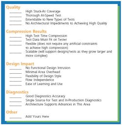
Adopting any new methodology is a costly investment and one that should not be undertaken without sufficient investigation. To minimize the risk of choosing the wrong solution, thoroughly scrutinize the methodology to see how it stands up to key criteria. Figure 4 is a sample checklist that you can use as you prepare to evaluate an embedded compression solution for manufacturing test.
About the Author
Michelle Lange is a marketing manager in the Design-for-Test group at Mentor Graphics. In 15 years at Mentor Graphics, Ms. Lange has held various positions in marketing, training, and technical publications, including 10 in the DFT group. Ms. Lange holds a B.S.E.E. from University of Portland and an M.B.A. from University of Phoenix. Mentor Graphics, Design-for-Test Division, 8005 S.W. Boeckman Rd., Wilsonville, OR 97070, 503-685-1768, e-mail: [email protected]
FOR MORE INFORMATION
on compressing test times
and data volume
www.rsleads.com/505ee-182
May 2005


