Test compression sounds like magic. Read on to learn how this trick is done.
Large, complex ICs are viable because their design meets test as well as functional requirements. Design for test (DFT) was only slowly adopted by designers until electronic design automation (EDA) companies provided tools that automatically inserted the necessary test structures. Generally, these DFT approaches are based on scan techniques and have little effect on the IC�s functional circuitry.
As designs have become larger and semiconductor manufacturing processes changed, the number of test vectors needed has exploded. IC size today often is in the millions or tens of millions of gates, but size alone has not caused the problem. Smaller geometries, copper interconnects, and low-K dielectrics have created new types of defects that also require additional vectors.
On the positive side, EDA tools cope well with very large designs, and, at least for these huge ICs, providing the necessary support for test no longer is an issue. After decades of EDA companies preaching the merits of DFT, it now happens automatically. However, so many test vectors may be required that no ATE is capable of testing the IC in a single pass.
This conundrum is not new although the scale has changed. In the early �80s, IBM realized that adding more and more memory to a tester wasn�t a viable long-term solution. Bernd Koenemann and others pioneered test vector and test result compression. Acronyms familiar to today�s test engineers were coined at that time: SRSG�shift register sequence generator, later termed PRPG�pseudorandom pattern generator; MISR�multiple input signature register; STUMPS�self-test using a MISR and parallel SRSG; OPMISR�on-product MISR to list a few.
At the 2001 International Test Conference (ITC) in Atlantic City, Dr. Koenemann described the OPMISR concept and discussed the results IBM had gathered from its application to real IC designs. Test vector data volume had been reduced by a factor of 10 and the overall test time by a factor of 2. Cadence Design Systems later acquired IBM�s EDA group and the test vector compression technology became the basis for Cadence�s Encounter Test Architect product.
Of course, other EDA companies also were developing solutions to the test data volume and test time problems. In addition, many academic research papers were published in 2001 and 2002, each exploring some aspect of IC test compression.
Under the Hood
All input-data compression schemes rely on the fact that test vectors largely contain irrelevant information. Other than a few critical so-called care-bits, the rest of the bits (don�t-care or X bits) contribute to fault finding only by accident. In the past, the automatic test pattern generator (ATPG) program filled these bits with random 1s and 0s, but the vectors still had to be stored in the ATE memory. Test vector volume reduction results from supplying the don�t-care bits in some other way.
Greatly increasing the number of scan chains within an IC helps reduce the test time. Even in a conventional scan-in, scan-out approach, a wide parallel interface requires fewer scan-in clock cycles than a narrow interface. On-chip compression of scan-out data further reduces test time and has a profound effect on scan-out data volume. For example, in the Cadence OPMISR scheme, if no faults are found, output data is reduced by a factor corresponding to the length of the scan chain: Only the final MISR signature is output at the end of each test pattern cycle.
Today, several EDA companies are selling test compression products that appear to have similar benefits. How does the user decide which one, if any, is right for his application? A review of some representative offerings is a good starting point.
SynTest Technologies
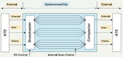
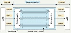
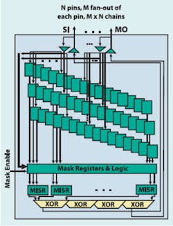
VirtualScan� is SynTest�s test compression tool. It can insert scan logic or add its distinctive broadcaster and compactor logic to designs that already have their scan chains defined. The exclusive-OR (XOR)-based logic breaks n long scan chains into n groups of N shorter chains, where N is the split ratio.
At the input end, the broadcaster logic distributes test vector data to each chain in a group of N from a number of different primary scan inputs. This technique provides greater flexibility than applying identical data to each of the N chains. Nevertheless, the applied data is constrained and may not be capable of simultaneously providing all the required care bits. In this case, additional patterns will be needed (Figure 1).
Figure 1. VirtualScan Block Diagram
Courtesy of SynTest Technologies
In a 2 million gate design example the company provided, a split ratio of N = 16 reduced the scan chain length from 3,718 to 233. Originally, 2,659 vectors were needed, and this expanded by 23% to 3,274 for the shorter chains. However, when total test data volumes are compared, the initial 316,357,184 bits (n = 16 scan chains � 3,718-b length � 2,659 tests � 2 scan-in and scan-out) reduced to 30,513,680, a ratio of 10.4:1 or a reduction of more than 90%.
XOR logic recombines each group of N chains into a single output stream or 16 streams in the 2 million gate example. In VirtualScan, one group of N chains has no effect on neighboring groups, which means that the ATPG can ignore only the bits in the scan-out data that were predicted to have X states. The entire test cycle isn�t invalidated by X states as occurs in some test data compression approaches.
At present, the tool supports a software-based compactor remodeling mechanism to eliminate aliasing and fault masking problems, ensuring an accurate fault coverage report.
The broadcaster and compactor XOR gates act as multiplexers to select data associated with parallel operation of the N short chains or concatenate N chains to reconstitute each original long chain. When a fault is detected, diagnosis may be aided by dealing with n long serial chains rather than n � N parallel short chains.
Broadcasting the same input data to several parallel chains is a feature of the Illinois scan (ILS) architecture. In A Case Study on the Implementation of the Illinois Scan Architecture, a paper presented at ITC 2001, the authors commented that many tests might not be possible when the original long chains have been segmented and that additional test vectors must be run with the short chains concatenated. However, they conclude that ILS is effective in reducing test data volume while maintaining a high fault coverage percentage.
In the 2 million gate SynTest example, fault coverage went from 94.8% as a baseline to 94.6% with N = 16 and to 94.5% with N = 32. It should be made clear that ILS uses a MISR to compact output data where VirtualScan uses only XOR gate logic.
Synopsys
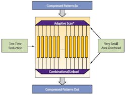
DFT Compiler MAX features what Synopsys terms Adaptive Scan architecture. This DFT synthesis tool inserts a large number of scan chains and accomplishes input data expansion by applying the same test vector bits in parallel to selected chains. Multiplexers ahead of the scan chains select data from the scan inputs, on the fly, for each scan chain. This means that distinct test patterns can be constructed for each scan chain where the control data is blended with the scan data (Figure 2).
In two examples provided by the company, 12� as many internal chains were used as there were scan inputs. A 1 million gate design originally used 28 chains and with Adaptive Scan used 336 and a 700-k gate design with 10 chains increased to 120. The actual test data volume reduction factors were 11.93 and 11.79 respectively, so a few more vectors were needed than if a perfect factor of 12 had been achieved. The results appear to support the premise that a more effective test pattern results from adaptive reconfiguration of scan cells.
An XOR logic output structure similar to Syntest�s compacts the results from a number of chains. Like VirtualScan, DFT Compiler MAX does not determine pass/fail on-chip.
Cadence
The OPMISR approach used in the Cadence Encounter Test Architect product addresses output test data volume compression. The number of scan chains is not unusually large and generally constrained by ATE channel limitations. What is different on the scan input is the option of multiplexing to allow the same physical pins to deliver the input test data to the scan chains and read out the compacted MISR signature at the end of each test cycle. OPMISR designs typically support twice as many scan chains as a traditional scan-in, scan-out design (Figure 3).
It�s not surprising that IBM and now Cadence have adopted an onboard MISR compression technique because, in addition to its ATPG-based test compression work, IBM was very actively involved in built-in self-test (BIST) development. Theoretically, BIST is the ultimate test data compression scheme: All test patterns are developed on-chip, and only a pass/fail indication is required as an output. In practice, BIST has had only limited production test success for several reasons.
BIST generally provides less test coverage than ATPG-based approaches and has been difficult to implement. It traditionally used pseudorandom patterns but more recently has been modified to accept externally applied seeds to produce better targeted vectors. BIST also is aided by test points inserted in the design and separate top-up ATPG vectors.
The most recent BIST design tools analyze the circuit under test to ensure that the detailed implementation of the PRPG will better address random-resistant parts of the design. BIST is popular in applications that require self-test after deployment.
Some ATPG-based test data compression schemes borrow either the front-end PRPG random data generation or back-end data compaction structures or both from BIST. OPMISR is an example of a BIST output MISR in an ATPG-based test approach.
A MISR is a linear feedback structure based on a shift register. Its output is similar to that of a cyclic redundancy code (CRC) generator to the extent that it develops a signature based on the effect of all the bits fed into it. If any bit is wrong, the signature will be different from the expected value, and a fault will have been detected. Obviously, if one or more of the bits scanned into the MISR is an X, the resulting signature will be meaningless.
The Encounter Test implementation of an OPMISR includes an X mask capability. This means that the ATPG can program MISR inputs to ignore predicted X values by forcing the relevant MISR inputs to a known state on a per-cycle, per-chain basis.
Because test results from all the scan chains are compacted on-chip into a single signature, output test data volume is almost entirely eliminated. By itself, compacting output data on-chip leads to a near 50% test-time reduction because only the input data must be clocked in bit by bit. Further test volume and test time savings result from input test data reduction.
The OPMISR plus (OPMISR+) scheme adopts the ILS technique to fan-out input test data to N short chains for each of n scan input channels. A separate MISR with its own X-masking register compacts the results from each group of N chains, and the signatures from the n MISRs are further combined by XOR logic to form a single output signature.
A 1.14 million gate OPMISR+ design example used both N = 5 and N = 6 to achieve a reduction in required tester cycles from 46,587,196 to 4,264,078, a factor of about 11:1 or 91%. Input test data was reduced by about the same degree.
Further reductions are possible by applying techniques such as run length encoding to the input test data. Depending on the ATE model chosen, a constant 1 or 0 can be repeated as fill data rather than generating a random sequence of values. This means that only the instruction to repeat a value must be stored, not the actual string of eight, 16, 32, or more identical bits.
Mentor Graphics
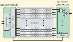
The TestKompress� product is based on a test pattern compression scheme the company calls embedded deterministic test (EDT) and was described in detail in the paper �Embedded Deterministic Test for Low-Cost Manufacturing Test� presented at ITC 2002. This technique inserts a test pattern ring generator based on a recirculating shift register with internal feedback. The ATE inputs to this structure are expanded by adding pseudorandom data, and the generator outputs are distributed to the scan chains via a phase shifter (Figure 4).
The test data reduction procedure starts by deterministically compressing the care bits within an incompletely specified test pattern, a so-called test cube. The technique used to do this effectively implements the inverse of the actions of the ring-generator decompressor, the phase shifter, and the scan chains. The overall scheme is deterministic because, after the vectors constituting a test pattern have been shifted into the scan chains, the care-bit values will be in the locations specified in the test cubes.
The ring generator is termed a continuous-flow decompressor because it is fed a small amount of data each scan cycle. For example, in a 32-stage generator, 4 b of ATE data may each be injected at two points in the ring via XOR gates. These gates are in addition to those needed to implement the polynomial that controls the nature of the pseudorandom sequence. Injecting this data will disrupt the normal sequence of states the polynomial would otherwise generate, and it�s the job of the ATPG to work out what information to provide to cause the desired disruption.
On the scan-out side, XOR-based logic is used to compact the test results from a number of scan chains. As many XOR trees are used as there are scan channels. In addition, logic and controlling registers are provided to eliminate multiple fault-caused aliasing as well as X-state aliasing. Because compacted data rather than only representative signatures are output, diagnostic efforts are simplified. Optionally, TestKom-press can include the capability to run the scan cells in a traditional scan-in, scan-out mode.
In a 2.1 million gate design, the original 16 scan chains of 11,292 cells were replaced by 2,400 chains of 80 cells. The original 1,600 test patterns increased to 2,238, but both test data volume and test time were reduced by a factor of 100.
Summary
It�s clear even from this high-level discussion of test data compression that the present schemes all achieve significant reduction of both tester cycles and data volume. Now that factors from 10 to 100 are available, compression has very much become a nonissue. The question is not can it be done but rather why aren�t all designers using it?
One aspect of these products that partially answers the question is ease of understanding. Test engineers understand scan-in, scan-out systems so, for example, SynTest�s VirtualScan probably would be easier to understand than a tool that used a MISR-based compactor. Unless an engineer had a BIST background, a MISR might be unfamiliar.
Diagnostics based on output signatures is different from diagnostics based on full scan-out data. A common solution is to reconfigure the scan chains after a fault has been found and run the test pattern again, this time scanning out the test result data for analysis.
Depending on the type of circuitry within a chip, it is true that some compression schemes may work better than others. So, an in-depth consideration of a test tool would need to include a review of its performance across many different IC designs.
Another impediment to adoption of test data compression is the lack of standards for test compression tools, even for relatively straightforward ILS. Until at least the more basic approaches are standardized, few vendors will offer cross-support.
The relationships between a single vendor�s ATPG, the test vector compression/expansion, the scan chain fan-out, and the compactor design rely on thousands of small, proprietary details. For example, although ILS is nonproprietary, if both vendor A and vendor B were to implement ILS, it only would be by chance that their tools for the two schemes were compatible.
If you�re not already using a compression tool, you soon may need to as your IC designs expand and new types of faults appear at smaller and smaller geometries. In lieu of a compression standard, your best source of information is your EDA company. Ask questions, read technical reports, and buttonhole the experts at venues such as ITC. Compression is real, it works, and if you�re not using it on a large design, you�re probably losing money for your company.
Additional Reading
Lange, M., �Adopting the Right Embedded Compression Solution,� EE-Evaluation Engineering, May 2005, pp. 32-40, https://www.evaluationengineering.com/archive/articles/0505/0505adopting_right.asp
FOR MORE INFORMATION
on the SynTest VirtualScan Test
Compression Tool
www.rsleads.com/507ee-176
on the Synopsys DFT Compiler MAX
Test Compression Tool
www.rsleads.com/507ee-177
on the Cadence Design Systems
OPMISR Test Compression Tool
www.rsleads.com/507ee-178
on the Mentor Graphics
TestKompress Test Compression Tool
www.rsleads.com/507ee-179
July 2005
