An industry expert addresses the debate of discrete components vs. external boxed filters for suppressing noise.
The analysis and suppression of electro-magnetic interference (EMI) generated from high-frequency switching converters are becoming increasingly important today. On the one hand, we have more EMC regulations. On the other hand, the switching frequencies are faster, and we are facing more functional issues. The EMI noise in power converters generally can be associated with the layout and design, but design and mechanical constraints can be limiting in many projects.
Increasing the converter power density is the main challenge of manufacturers. As a result, the switching frequencies are higher than ever, which leads to more high-frequency noise. This applies to both differential and common-mode noise.
In today�s approach, trial-and-error methods often are used to find the proper suppression solution. While this is ultimately successful, it is time-consuming, expensive, and often difficult to combine with optimized performance of the power supply.
For a cost-effective and timesaving approach to design, the EMI characteristics of a switch-mode power supply (SMPS) need to be analyzed at an early stage in the project. The most important aspects to examine are the high dv/dt and di/dt slew rates in the SMPS and the circuit layout itself.
Noise Analysis
While a number of topologies exist for SMPS, the causes of electromagnetic noise are similar in all of them. For example, Figure 1 shows the circuit diagram and the PCB layout of a typical power supply.
One of the critical points for generating noise is the drain node of the MOSFET with its high dv/dt and di/dt slew rates. Since most of the noise is caused by parasitic components in the circuit, one highly critical factor for the reduction of EMI noise is the layout geometry of the boost circuit. On the PCB, we find parasitic inductances in the tracks and connection leads and capacitances to ground, resulting in two different forms of interference: differential-mode (DM) and common-mode (CM) noise.
The CM noise is directly related to stray capacitance (CM capacitance). CM currents are equal in phase on the hot and return paths and return to the source via the system ground.
Since only the drain node of the MOSFET has a high dv/dt slew rate and the MOSFET is mounted flat on the PCB, the major CM capacitance in this circuit comes from the capacitance between the drain node trace and the ground plane. If required, this capacitance can be calculated according to the analytical formula or the finite element analysis (FEA) method. Typical CM noise occurs in the higher frequency range.
DM currents are opposite in phase on the hot line and the return path. The parasitic inductance combined with the high di/dt slew rates in the pulsed switched currents will introduce DM noise. DM interference is directly related to the switching frequency of the SMPS.
Noise Reduction
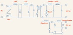
If there is one power supply of universal interest, it is a standard power supply for PCs. The circuit diagram of such an SMPS is shown in Figure 2. To show the influence of various suppression components, some of the additional onboard filtering devices have been removed without altering the actual function of the power supply.
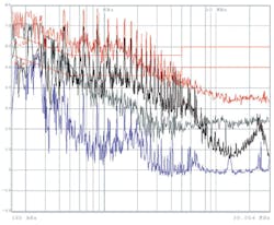
The power supply has been measured in four basic configurations shown in Figure 3. The capacitors help suppress noise especially in the upper frequency range. This also is what we would predict since the impact of the Y capacitors (to ground) is higher than that of the X capacitors (between lines).
Grey = only inductors. Blue = complete filter solution.
The results with the capacitors are about 10 dB lower up to 5 MHz and up to 25 dB lower between 5 and 30 MHz. However, we also can see a strong resonance point at about 24 MHz. Capacitors alone are effective but might not be stable across the whole frequency range.
The effects of the choke can best be seen in the frequency range from approximately 500 kHz to 7 MHz where the noise reduction is up to 30 dB. The actual frequency range for chokes depends mainly on the material of the core and the winding technique used.
An interesting effect can be seen in the complete filter solution. The same choke and capacitors have been used as before, but the resulting total noise reduction now is significantly better than with the single components. The attenuation moves between 10 dB at the worst point and more than 50 dB at the best.
One additional advantage of a boxed filter can be seen here: The housing works like an additional shield for high frequency and prevents coupling of noise signals at the power entry module. While the good result with the filter components in the box might look random and coincidental, it is the result of simulation and good engineering practice combined with experience. As is always true for EMC, there are no universal rules, and the selection and positioning of suppression components can vary with the application.
Discrete Components and Boxed Filters
Noise suppression in SMPS often is considered a necessary evil. Maximum suppression with minimum space requirements and no additional temperature rise is expected at the lowest possible cost. The common discussion arises whether suppression should be realized onboard with discrete components or with external boxed filters.
Comparatively boxed filters are optimized in terms of EMC design and supplement the suppression effects of the components by additional shielding of the box. However, they take up a little bit more space and come at a higher material cost.
In a useful comparison between the two solutions, do not forget the administrative cost. While the material cost is lower for discrete components, the administrative work increases. Several components need to be stocked, and several suppliers need to be administered. A decision based solely on material cost is not always the most reasonable approach.
Summary
SMPS, by definition, produce high amounts of electromagnetic noise. The parasitic components of the MOSFET switches as well as the equivalent series inductance (ESL) and equivalent series resistance (ESR) of all components lead to high-frequency interference, which exceeds common EMC limits and can cause functional problems.
DM noise, typically in the lower frequency range and associated with the switching frequency, and CM noise, relating to the higher frequency range, need sophisticated suppression solutions. Here size, cost, and efficiency of the suppression circuit top the list of requirements.
While the switching frequencies of SMPS are continuously increasing, the market demands a constant decrease of size, price, and development times. The development cycle typically is so short that engineers must optimize their functional designs quickly. Implementing the necessary noise suppression adds another factor to the equation that can increase development time.
The ongoing discussion is whether suppression should be done with discrete components or external boxed filters. While discrete solutions look less expensive in the beginning, this often is a false conclusion. Considering the total cost of ownership and performance, a boxed filter generally is a better solution.
About the Author
Wolfgang L. Klampfer is the manager of Schaffner�s Training Center at the corporate headquarters in Luterbach, Switzerland. Before joining the Schaffner group, he gained EMC experience at the German EMC laboratory of Sony and in the Japanese subsidiary of T�V Rheinland. Schaffner EMC, 732-225-9533, [email protected]
August 2005


