Maximizing the Performance Capability of Conducted Immunity Test Systems
There are many subtleties that need to be considered when performing conducted immunity testing.
Present conducted immunity test systems are notoriously inefficient, with 75% of the available system power intentionally dissipated in a high-loss attenuator. This situation exists simply because a source intended to be operated into a 50-? system is injecting RF into a product incapable of presenting a 50-? characteristic impedance. To solve the mismatch situation, a high-power, high-loss attenuator is inserted between the system components. This is the bulldozer approach at its worst. Thankfully, more elegant and efficient solutions exist.
Test Description and Background
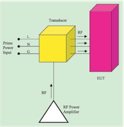
A typical conducted immunity test uses a transducer to couple RF power from a power amplifier onto the conductors of the AC power cord of the equipment under test (EUT). Figure 1 shows a simplified test setup.
The RF is impressed equally onto all three wires of the AC input to simulate the effect of a nearby field interfering with the EUT and its power cord. Not shown but always present is a means of limiting the amount of RF entering the AC distribution network. Also, as a precaution, the length of AC cable actually carrying the RF is kept short to reduce the likelihood of radiation.
It is inevitable that products will be located in the vicinity of an intentional RF emitter. The field generated by the emitter will couple into the product and its AC power cord, and since the wires inside the cord are parallel and close together, identical currents will couple into each wire: live, neutral, and ground. This results in a common-mode interference signal.
The currents will travel toward the product and into the local AC distribution network. Not designed for high- frequency use, the power cord and AC distribution network have high attenuation per unit length. The interference signal traveling away from the product is dissipated by this attenuation and assumed to have no further effect. The signal moving along the cord toward the product produces a specified voltage level at a position close to the product.
Power-cord lengths vary in practice, so it is assumed that the electrical length of the power cord/product combination makes an efficient receive antenna at any test frequency. Consequently, susceptibility tests are performed across the entire lower RF frequency spectrum, normally 150 kHz to 80 MHz. Also, it is assumed that at this lower end of the RF frequency spectrum conducted interference via the AC input is the dominant mode of entry into the EUT.
Some of the key requirements a conducted RF immunity test must meet are the following:
� The system has to be technically feasible given the available technology.
� It has to produce repeatable results.
� It has to be commercially viable.
Regarding available technology, the main challenge is identifying and assessing appropriate transducers. Three transducers are suitable for this test, each with particular strengths and weaknesses.
The most straightforward is the current transformer. Used in the bulk current-injection method of coupling RF to a power cord noninvasively, its advantages are simplicity and small size. The disadvantages are low coupling factor (lossy) and no built-in means of preventing RF from entering the AC network.
The third transducer is a coupling/decoupling network (CDN). This is intrusive because it connects between the power cord and the EUT. As implied in the name, it contains a circuit to couple the RF test signal to the power cord conductors and a circuit to prevent RF from entering the AC network.
Its main advantages are control of the RF source impedance, a built-in RF blocking capability, and excellent coupling factor. On the downside, it presents a poor match to the power amplifier, and tailor-made power cords are required to allow connection close to the EUT.
Regarding commercial viability, the capital outlay for a recommended conducted immunity test system is approximately $45,000. That�s not too outrageous when compared to an RF radiated immunity system. An important fact is that once the decision is made on the most appropriate transducer for a particular EUT, the tests require only a single calibration and test run.
As for repeatability, since the test system carries unshielded RF signals at nontrivial levels, it is sensitive to variables such as the electrical length (measured in wavelengths) of the cable, system impedance mismatches, and the proximity of system components to ground planes.
Transmission Line Theory
For electronic products, as the frequency of operation increases, parasitics begin to dominate and inductors can behave as capacitors (due to the finite capacitance between the turns) and capacitors can behave as inductors (due to the finite series inductance of the leads). At still higher frequencies, component sizes and interconnection lengths start to approach one-tenth of the signal wavelength, which is the domain of transmission line theory.
With transmission line theory comes the concept of the power wave. Arrangements of conductors designed to transmit power now are seen as having distributed inductance and capacitance per unit length and a characteristic impedance dictated by the size and spacing between the conductors and the dielectric between them. Characteristic impedance usually is expressed as Zo.
An RF power wave launched onto a transmission line travels along that line irrespective of how the line is terminated. If the transmission line is terminated in a resistor (or resistive circuit) with a value equal to the characteristic impedance of the line, maximum power transfer takes place, and all the power is dissipated in the termination. Any other type of termination will result in less than maximum power transfer, and the power not transferred is reflected back along the transmission line.
With a forward wave heading to the termination and a reflected wave heading back toward the source, constructive and destructive interference takes place along the line resulting in a standing wave. These waves have peaks and nulls and are given the name standing because the nulls remain in a fixed position while the peaks pulse up and down from maximum to minimum at a fixed position half way between the nulls. The peaks and nulls occur every quarter wavelength.
The AC Power Cord as a Transmission Line
At RF frequencies, the AC power cord is a lossy transmission line. At low frequencies, AC network analysis applies. As the frequency increases, the impedance looking into the cable decreases because of the parallel capacitance between the conductors. As the frequency is increased still further, there is a transition band where the series inductance starts to take effect, and the decreasing input impedance asymptotically meets the constant characteristic impedance.
Once beyond the frequency where the characteristic impedance applies, the impedance stays constant irrespective of frequency and cable length. For the AC power cord, the transition band probably starts around 100 kHz and ends somewhere around 1 MHz.
An AC filter is designed to block high-frequency common-mode interfering signals, so it is a fairly safe assumption that most of the power wave will be reflected back on the live and neutral wires. The EUT chassis is not the ground reference of the test system, and no deliberate impediment to RF signals has been designed into this termination. What happens to the power wave when it impinges on this termination probably determines the susceptibility of the EUT to conducted RF interference. The question is how does the existence of a standing wave affect performance?
When a standing wave exists on a transmission line, the impedance is no longer Zo at all points on the line. Low impedance points coincide with the position of wave nulls, and high impedance points coincide with the position of wave peaks.
This impedance variation can affect the repeatability of the immunity test since the RF coupling is at a fixed point on the line. The RF transducer has finite source impedance, and the amount of RF will change as the line impedance changes.
Therefore, in conducted immunity test systems, the transducer is located close to the EUT (always less than one tenth of a wavelength at the highest test frequency). This provides a constant-impedance point with frequency, but since this point on the power cord also is close to a point of high reflection, the measured value of the constant impedance will be different than the 150-? characteristic impedance�the impedance used to calibrate the system.
Obtrusive or Nonobtrusive
An ideal nonobtrusive measurement is where the sampling mechanism, when introduced, causes no changes to the circuit being measured. Once an immunity test system has coupled RF into a power cord, other system components should not cause changes within the test system.
To prevent RF from entering the AC network, a high-frequency choke is placed in the power cord close to the transducer. For a repeatable immunity test process, the added test-system choke should be absorptive (dissipative) to prevent reflection of the outbound power wave. This allows closer replication of real-life conditions where the outbound wave is dissipated or radiated by the lossy AC network.
Calibration
For system calibration, RF is impressed onto all three conductors of a short length of AC cord, and the RF power levels are recorded for each test frequency. All three conductors are shorted together at each end of the power cord. A simple 100-? resistor is placed in series with the RF, purportedly to match the 50-? test system to the 150-? characteristic impedance of the EUT.
From an AC network analysis point of view, the calibration process makes sense. From a transmission line point of view, the power wave has to cross four planes of discontinuity, and the short circuits on the ends make a lot less sense. Overshadowing all of these factors though is the apparent departure from what the test is supposed to be replicating.
In practice, the voltage generated on a power cord as a result of coupling to a local field will be entirely dependent on the strength of the field. For any calibration procedure, the external field strength should be a constant, the frequency should be an independent variable, and the voltage should be the dependent variable.
The ideal solution is a regular RF radiated-immunity test setup that uses an antenna to create the fields and an anechoic chamber to control and contain them. Unfortunately, this test setup is unsuitable for creating fields at lower frequencies.
Actual Test Runs
To prevent an over-test situation, the current flowing into the EUT is monitored at all test frequencies. If it exceeds a certain level, the voltage is reduced until the current is that which would flow into a 150-? EUT impedance.
Unfortunately, this seems to fly in the face of the entire purpose of the immunity test since the frequencies at which excess currents are drawn could well be the very frequencies to which the EUT is most susceptible. There is no way of knowing whether the excess current is because of a test system peculiarity or the EUT.
There is a risk that reducing the test level may mask susceptibilities that show themselves when the product is located next to a real-life radiator. These radiators do not back off just because a nearby product has an unresolved peculiarity at the radiation frequency.
The transducers require only a few watts of RF power, yet most conducted immunity test systems have amplifiers with many tens of watts. This situation exists simply because RF power is lost as heat in the recommended 6-dB attenuator between the amplifier and the transducer.
Furthermore, the premium price paid for the claimed feature that an amplifier is immune to reflected power also is money ill-spent. The amplifier in this system configuration will never see reflected power of more than one-sixteenth of its forward power capability.
So why the 6-dB attenuator? We must conclude that the conducted immunity test system is sensitive to the output impedance of the amplifier. Note that no such attenuation is put in the field generation path of a radiated immunity system.
Possible Alternative Approaches
For system calibration, a possible alternative is to take advantage of the reciprocal nature of RF. An external field couples RF onto the power-cord conductors. Conversely, RF on the conductors creates an external field. By recording the amount of RF power required to create a specific field strength, the requirement of making frequency the independent variable and field strength a constant is met.
A TEM cell (adapted to accommodate the cable) would be suitable for measuring the field external to the cable. TEM cells can produce fields at low frequencies. The RF at the load end of the cable would need to be dissipated to prevent mismatch conditions.
Characterizing the calibration cable needs to be factored in since the dielectric constant and the conductor resistance (skin effect) may well change with frequency. Obviously, the calibration cable should be of the same type as will be used with the EUT.
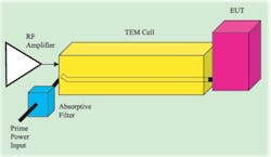
Alternatively, and perhaps ideally, the actual test run should be conducted with the entire EUT power cord inside a suitable TEM cell configured for radiated immunity testing. The calibration then would simply consist of setting the field strength inside the TEM cell as shown in Figure 2.
Staying with the present immunity system, consideration could be given to a different method of matching the amplifier to the input impedance of the transducer. Impedance transformers include components such as RF transformers, transmission line transformers, and baluns. In fact, the broadband amplifier driving the system contains several of these components.
The system might behave better with a higher source impedance, say 300 or 600 ?. Connectorized bolt-on impedance transformers could be made available for each type of transducer.
A more radical approach would be to dispense with the AC power cord altogether (for the purposes of the test) and inject RF directly into the terminals of the AC filter. The internal DC voltages required by the EUT would be supplied by separate RF-isolated sources. Most rectifier/transformer stages pass RF signals unaltered. This approach, if feasible, is more for companies that see EMC testing as part of thorough product characterization, since the connections for such testing would need to be incorporated early in the design stage.
Conclusion
I have not mentioned other EUT ports such as those connecting to auxiliary equipment. Nor have I mentioned cable types other than the three-wire AC cord. These exclusions are an attempt to keep a very complex subject simple and also because the main principles discussed apply equally well to other ports and cable types.
It is difficult to resolve unpredictable system behavior when part of the system includes a section of lossy cable of unknown impedance that is injected with RF signals over the cable�s transition band as well as its constant impedance band. Not helping the situation is the fact that the RF is injected in common mode.
About the Author
Thomas Mullineaux, the chief writer at HighTechWriter, is an RF engineer with 15 years experience in leading design teams. HighTechWriter, 3332 Florista St., Los Alamitos, CA 90720, 562-400-4501, e-mail: [email protected]
September 2005


