Volts, amps, and ohms haven�t changed a lot in the last few years, but that hasn�t held back advances in the instruments that measure them. Traditional benchtop digital multimeters (DMMs) now have dual and graphical displays, more types of measurements, wider ranges, faster speeds, and a choice of several types of remote interface.
These enhancements may allow you to reduce the number of instruments required in a test setup. For example, many DMMs measure frequency, period, temperature, and capacitance in addition to the basic volts, amps, and ohms. Higher throughput often reduces the cost of test, and further savings may result from using the remote interface best suited to your test requirements. In addition to RS-232 and GPIB, LXI and USB 2.0 also are offered on some new DMMs.
Something as straightforward as a dual display can make a big difference in efficiency. With a dual display, a DMM can simultaneously present peak and rms measurements, for example, or monitor the level of an AC input while its frequency is being measured. A graphical display adds histograms and value vs. time trend plots as well as multiple reading capabilities.
Yet, as important as these improvements are, many fundamental things have not changed. For example, the highest DC accuracy still is obtained at a relatively slow reading rate. Integrating for an integer number of AC power line cycles (NPLC) reduces the contribution of noise from this source.
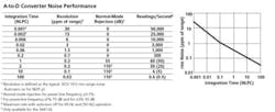
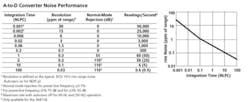
As shown in Figure 1, new ADC technology and system architecture have made possible previously unattainable reading rates. Of course, there are trade-offs. As the table shows, normal-mode rejection relies on integrating for at least one PLC. The 60 readings/s rate directly corresponds to an integration time of one PLC. Faster operation is possible, but as the graph shows, rms noise increases significantly. Conversely, it reduces for longer integration times.
Click here to see larger image
This effect often is acknowledged by claiming fewer digits of resolution at higher reading rates. The comparison chart that accompanies this article lists reading rates for resolutions from 4� to 6� digits. The one-half in these designations refers to the most significant digit that reads only zero or one.
The reading rate also can be increased by disabling the DMM�s autozero function. To maintain high accuracy, many DMMs disconnect the input signal and measure the zero level before making an actual measurement. Any zero offset is subtracted from the signal measurement and the result displayed. In the Agilent Technologies 34411A instrument, for example, the reading rate doubles from 25,000/s to 50,000/s when autozero is disabled.
If all the signals being measured at a high rate are within the same meter range, autoranging isn�t a concern. However, if the signal value can change by large amounts, additional time will be lost when the meter changes range. How helpful a DMM�s high reading rate is depends on your application and the organization of your test software.
Please click here for Benchtop DMM Comparison Chart.
The Details Behind the Chart
Calibration Interval
Major capabilities are listed in the comparison chart, but each specification consists of much more than a single number. An obvious consideration is the calibration interval. Two periods are noted in the chart, 90 days and one year, although several manufacturers� datasheets include 24-h specifications as well. Some datasheets don�t mention calibration interval at all.
Overrange and Maximum Input
Overrange is the amount by which you can exceed the maximum input for a given range while still making accurate readings. High-resolution DMMs often include a 20% overrange feature that makes the instrument easier to use. To get the best accuracy, you need to choose the range that is just large enough to handle your signal�s peak excursions. Accuracy isn�t quoted for different amplitudes within a range, but typically there is a 5% or 10% of range lower limit given. Below this value, the specified accuracy will degrade.
Two very important exceptions to overrange capabilities are the highest DC and AC ranges. For example, Agilent, Keithley, and Fluke allow 20% overrange except on the 1,000-V DC and 750-V or 1,000-V AC ranges. On these ranges, the maximum is the range value. Conversely, B+K Precision doesn�t state an overrange value for lower ranges on the Model 5292 but does allow 5% overrange on the highest DC and AC ranges.
A related consideration is the maximum level that can be applied to any range. In an autoranging instrument, you should be able to apply the maximum safe signal at any range setting. Fluke simply states that 1,000 V DC or 1,000 V peak can be applied to any Model 8845A voltage range, completely eliminating user uncertainty.
Temperature Coefficient
DMM datasheets often list a temperature coefficient to further qualify accuracy. This may be a single percentage of reading or two values relating to percentage of reading and range. Errors due to temperature arise when the operating temperature is significantly different from the temperature at which the DMM was calibrated. This sensitivity can be seen in some datasheets where a 90-day accuracy is specified within a �5�C band around the nominal 25�C calibration temperature but a higher accuracy 24-h specification requires a tighter �1�C band.
True rms Considerations
All of the DMMs listed in the comparison chart provide a true-rms AC measurement. This means that nonsinusoidal waveforms will be measured correctly. Some DMMs specify both AC-coupled and AC+DC modes. AC+DC provides the true rms value of the total waveform. AC-coupled operation measures only the AC component of the waveform. If the DC level changes, additional settling time may be required for the DC blocking capacitor to charge or discharge.
In either mode, three things limit performance. Because accuracy varies with frequency, the overall AC frequency range may be listed as a series of bands, each with a separate accuracy. This implies that different parts of a complex waveform will be measured with different accuracies. Parts of a signal containing frequencies beyond a meter�s bandwidth will be attenuated.
A related item is crest factor or the ratio of the signal peak to its rms value. Typically, DMMs remain accurate up to a crest factor of about 3.0. A fortunate byproduct of the technology that enables faster reading rates in some DMMs is increased crest factor. For example, the Agilent Model 34410A/11A specifies a maximum crest factor of 10:1. Fluke and Keithley each list 5:1.
However, there is more than the obvious 2� difference. Because of the way the Agilent ADC samples the signal, a high crest factor does not affect accuracy. Keithley�s Model 2000 DMM requires a 0.4% of reading accuracy reduction for crest factors between 4.0 and 5.0. Fluke�s Models 8845A/46A list a 0.5% of full-scale accuracy reduction for the same crest factors.
In addition, there is a maximum volt-hertz (V-Hz) product that limits the amplitude and/or frequency of inputs, typically on the highest AC range. Fluke, Agilent, and Keithley all specify a maximum 8�1077, and for common-mode inputs, 1�106. V-Hz product. This means, for example, that a 500-Vrms AC sine wave signal is limited to 160 kHz. B+K Precision further qualifies the Model 5492�s V-Hz product separately for normal-mode inputs, 2�10
AC Response Time
Many DMMs use a precision analog circuit to determine the rms value of a signal. While the result may be accurate, the circuit has a slow response to cope with low frequencies. For example, B+K Precision claims a 1.2-s response time for the Model 5492. In contrast, DMM architectures that sample the signal at a high rate may calculate the rms value. This approach is used in the Agilent Model 34410A/11A DMMs and claimed to be four to 10 times faster.
A selection of AC filters is available on some DMMs. These are bandpass filters that typically all have the same upper cutoff frequency but different lower cutoffs. The filter removes low-frequency signal components, allowing a faster reading rate. For example, Agilent�s Model 34410A/11A achieves 6�-digit reading rates of 50, 150, and 500 Hz with lower filter cutoff frequencies of 3, 20, and 200 Hz, respectively.
Resistance
The DMM�s test current develops a voltage across the resistance being measured. If that voltage is too high, semiconductor junctions in devices attached to the nodes being contacted can become forward biased, possibly corrupting readings. For this reason, as well as to minimize any resistance drift caused by self-heating, DMMs use as low a test current as practical.
At resistance values below 1 M?, Agilent, Fluke, and Keithley limit the developed voltage to 1.0 V. Above 1 M?, the voltage can be as high as 5 or 10 V. Hioki�s 5�-digit Model 3239 allows up to approximately 2 V across any resistance less than 100 M?, although in the DMM�s low-power ohms mode, the maximum voltage developed is approximately 0.2 V across resistances up to 2 M?.
Many datasheets qualify conditions under which certain specifications apply. For resistance, it�s common for a 4-wire (Kelvin) connection to be required to meet the published accuracies. Agilent, Keithley, and Fluke suggest that 0.2 ? be added to 2-wire measurements to account for the test lead resistance. B+K Precision recommends use of a shielded test cable for resistances above 120 k?.
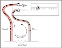
Fluke has developed an innovative set of test leads that bundle two insulated wires in each lead (Figure 2). Further, the electrical separation continues through a special banana plug and into the DMM�s input circuitry. Using these 2�4 wire ohms test leads actually makes a Kelvin connection to the DUT.
Because devices have become so small, it can be difficult to make contact with four separate probes, especially by hand. This approach solves the problem, but a degree of compromise has been necessary. The company recommends adding 20 m? to the DMM reading to account for slightly less than perfect Kelvin performance.
Current
The voltage across a precision shunt resistance is measured to determine the current flowing through it. This means that the act of measuring current creates a burden voltage that may or may not interfere with operation of the current sourcing circuit. In other words, the circuit being measured must have sufficient voltage compliance so the DMM�s burden voltage does not significantly alter the measured current value.
As an example, consider measuring the current flow in a 0.5-? resistor driven by a 1.5-V battery. Batteries are voltage sources with zero compliance, so even a very small burden voltage will cause a measurement error. Keithley and Agilent use a 0.1-? shunt resistance on the 3-A range, which means that you actually are measuring the current flow through a 0.6-? load or 2.5 A. This reading is 16.6% below the correct 3-A value. In contrast, Fluke uses a 0.01-? shunt on the 1-A, 3-A, and 10-A ranges. With this value, the reading will be 1.5/0.51 or 2.94 A: an error of -2%.
AC current ranges are easily extended to hundreds or thousands of amps by using a clamp-on current probe. Typically, such a probe is characterized by a sensitivity factor with units of mV/A. For many DMMs, you need to remember this factor to convert displayed volts to actual amps. Hioki�s Model 3239 has a built-in feature that automatically makes the conversion after you enter the type of current probe you are using.
Datasheets
A comprehensive datasheet is a weighty document with many footnotes because a large number of details affects accuracy. Also, as DMMs gain more functionality, new measurement capabilities and conditions all must be addressed.
Generally, lower cost instruments aren�t accompanied by a full set of specifications. This is not necessarily a problem for 4�-digit DMMs where high accuracy and precision are less of a concern than with 5�- or 6�-digit instruments. Nevertheless, a very compact specification listing only bullet points is cause for concern. You cannot possibly know how a DMM will behave under all conditions from so little information.
New Features and Future Trends
Several factors are affecting how modern electronic products are being designed and manufactured. To better address these requirements, new DMMs provide improved functionality, accuracy, cost, and user convenience in varying proportions. Hilton Hammond, marketing manager for precision DMMs at Fluke, said, �Business demands are driving engineers to design higher quality devices at lower costs. It follows that more thorough and detailed testing is required to find potential problems in circuits. The graphical display in the 8845A/46A models supports real-time analytical modes such as statistics and Trendplot� that help to simplify decision-making.�
Keithley has extended traditional DMM functionality by integrating precision switching and control in a single high-channel-count chassis for data acquisition applications. Of course, such an approach can save rack space compared to a system composed of several separate chassis. More importantly, integrating the functions likely to affect signal integrity ensures that the specified overall accuracy will be achieved and maintained.
The Model 2700 DMM provides two expansion slots capable of supporting up to 80 differential input channels. The Model 2701 is similar but provides a 10/100Base-TX Ethernet interface in place of GPIB and has faster scanning and triggering with a much larger reading buffer. The Model 2750 increases the number of input channels to 200 via five expansion slots and features a dry-circuit ohms capability. In this measurement mode, the voltage across an unknown resistance is limited to <20 mV.In contrast to Fluke and Keithley, Agilent has opted for speed. With a new high-sampling rate architecture have come several valuable capabilities. A 10,000-reading/s rate combined with very short trigger latency means that fast transients can be acquired and recorded. Further, signal detail at a different part of the waveform can be acquired by using pre- or post-trigger delay as you would with a DSO.
The Model 34411A�s 50,000 readings/s maximum rate together with the meter�s wide bandwidth allow electrical or mechanical signals with up to an 8-kHz bandwidth to be acquired with 6� oversampling. Having only a single channel, this DMM can�t displace multichannel data acquisition systems. Nevertheless, high-speed sampling applied to a few signals is a powerful tool in both the design and production phases of product development.
�DMMs will continue to integrate more functionality as processing costs decrease,� said Mike Hawes, DMM product manager at Agilent. �For example, the Model 34410A/11A uses digitized data with an anti-alias filter for AC measurements, technology that eventually might provide low-frequency spectrum analysis within a DMM. In another example,� he continued, �a new IC handles LXI, USB, and GPIB interfacing, providing greater system flexibility at low cost.�
Conclusion
It�s hard not to get excited about volts, amps, and ohms if you often need to precisely or very quickly measure them. Today�s DMMs really do deliver on your expectations. For example, speed and accuracy traditionally have been mutually exclusive requirements, but simultaneously satisfying both finally has become possible.
In addition to providing better quality measurements more quickly, modern DMMs generally present measurement results in a more useful way. It�s a matter of providing information about the signal rather than just displaying acquired data. All DMMs can measure voltage. A DMM that compares the present value to a stored value or displays the statistical distribution of many similar measurements represents a different class of instrument.
If DMMs actually evolve as the leading companies have indicated, you may eventually need fewer types of low- to medium-speed instrumentation. But, why wait until then? Now�s the time to re-evaluate test requirements with a view toward the new and improved features of today�s DMMs.
February 2007


