Vibration testing emerged in the early 1960s as electronics systems became more complex and widely available. This led to a need for greater reliability, with one of the major early adopters being the manned mission to the moon.
Prior to the Apollo missions, the levels of vibrations experienced by spacecraft weren�t fully understood, nor was the potential effect of vibration on electronic assemblies. A key and unfortunate event was the Apollo module fire in January 1967 in which three crew members were killed. This prompted NASA to review its test programs. As a result, the vibration test requirements were increased in both duration and intensity, and various other changes were made in the design, manufacturing, and testing processes.1
We now know that vibrations affect everything from solder joints to the actual flexing of connecting cables and circuit boards. This can lead to catastrophic failures that could affect human safety and subsystem performance or to unreliable consumer electronics and higher warranty costs. The Apollo fire brought environmental testing into the mainstream of engineering design.
Electrodynamic shakers are based on a conventional loudspeaker design. The earliest electrodynamic shakers were, in fact, high power speakers like those used in music concerts, with the diaphragm replaced by a flat surface onto which the test piece was mounted.
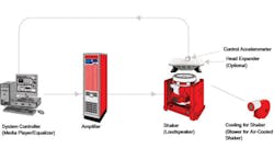
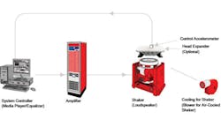
The vibration test system still operates in much the same way as a conventional audio system. The test data is played and controlled on a system controller through an electrodynamic shaker with an amplifier providing the required power for the displacement/acceleration/force
(Figure 1).
Figure 1. Typical Vibration Test System
Test systems are used in open- and closed-loop modes. In both cases, accelerometers measure the forces being generated at the shaker table and at various points on the test piece.
Technology Advances
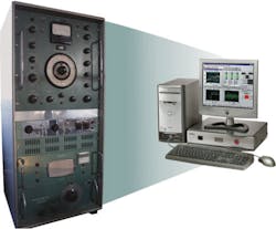
The technology involved in building these systems has greatly improved since those early days. Early amplifiers needed water to keep them cool while generating the power required to drive a shaker. This added to the size of the equipment since the electronics also were physically much bigger than they are today (Figure 2).
Figure 2. Scale of Changes: Vibration Controller From 1960s Compared
With Modern Controller
Water-cooled shakers are still widely used. They have an advantage over air-cooled shakers where high forces are needed or for very large payloads. In these cases, a great deal of heat is generated in the moving parts of the shaker, which is more effectively removed by a water circuit. Water-cooled shakers also are used in clean-room environments where air and dirt particles blowing around the test equipment are not desired, such as in aerospace/satellite testing applications.
The materials in the shaker itself also have improved. Composite materials now replace magnesium to produce lighter, stronger armatures. The reduction in armature weight translates to an increase in force being available for the DUT.
Design tools also have improved greatly, with much more powerful computers and software enabling engineers to more accurately predict the responses of the tables, fixtures, and test equipment over a wide range of conditions.
Which Shaker System Do I Need?
This is a question that most engineers ask when trying to specify a system. Quite often, there is no easy answer. The system requirements depend on the DUT and the test specification to which it is to be subjected. The first stage would be a simple calculation, Newton�s Second Law of Motion, to give an approximate force rating of the shaker required:
where: F = Force (lbf)
m = total moving mass including armature, fixings, fixtures, and
payload (lb)
a = acceleration (g)
This calculation is only an approximation because it doesn�t factor in the dynamic behavior of the DUT such as overturning moments.
The physical size of the DUT plays a significant role in determining which system will perform the required tests. For example, satellites are large and dynamically complex shapes, and loading on the shaker will change depending on whether the solar panels are open or closed. This may mean that a head expander is required to provide a suitable mounting platform.
Newton�s Third Law also applies: For every action there is an equal and opposite reaction. The forces exerted into the payload in the vertical axis also will be exerted into the floor of the building. This must be countered to prevent structural damage to the building, and there are a number of ways this can be done.
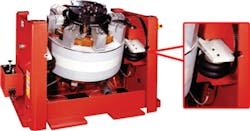
The most common method is to have some form of isolation between the shaker and the floor. This usually is in the form of air bags mounted between the shaker and its support trunnion and between the trunnion and the floor mounting plates. These air bags do affect the lower frequency limits of any vibration tests (Figure 3).
Figure 3. Air Isolators Located Between Shaker and Mounting Trunnion
With the air bags in place, the lower limit is ~5 Hz. For testing at frequencies lower than this, the air bags are locked out, which means that although the tests can be run at frequencies as low as DC, another method for absorbing the forces must be considered.
The addition of a seismic mass below the shaker enables low-frequency testing down to DC. The seismic mass is a large concrete block that absorbs the force and also may be supported by springs for additional isolation.
Shaker Configurations
Single Shaker
The single shaker is, by far, the most common configuration used directly in the vertical mode or in the horizontal with a slip table. Vibration levels range from 9N (2 lbf) up to 289kN (65,000 lbf) using permanent magnets or air- or water-cooled electrodynamic shakers.
There are a multitude of applications and industries for single shaker systems. They are used to mix solutions in pharmaceuticals, to test medical devices and aerospace equipment, and to perform modal analysis of large structures such as jet engines.
An interesting application was a study into human reflexes using a small shaker to stimulate the Achilles tendon. This allowed a repeatable force to be applied so the reactions of the subject could be measured.
Multi-axis testing is becoming increasingly common because it enables the DUT to be tested in all three axes, giving a more thorough test than just shaking in the vertical axis. It is limited because it still is a series of single-axis tests with the test piece repositioned for each new axis.
Simultaneous three-axis testing requires a complex bearing assembly to couple three shakers together, one for each axis. Although this has been done in a number of applications, it is complex and expensive. It is, however, the only true way to replicate real-world conditions.
Slip-plate sizes typically range from 600-mm2 to 1,900-mm2 although special tables have been manufactured up to 3 m x 1.9 m. These large tables are used primarily for testing satellites and increasingly with multiple shakers possibly in a push-pull configuration.
Dual Shakers
The dual-shaker method tests long pieces such as missiles and fiber-optic repeaters used in undersea cables. This approach enables a more accurate vibration profile to be applied to the test piece than is possible with a single shaker. As an example, the nose of a missile will experience lower-level vibration caused by air turbulence while the tail will be exposed to more severe vibration caused by the rocket engine and additional turbulence created by the control planes.
A single shaker could be used if a suitable fixture were created to support the DUT at each end; however, the vibration signal applied would be the same at both the nose and tail ends and not representative of real-world conditions. The added mass of this fixture also will reduce the force available from the shaker, which possibly would lead to the need for a larger shaker.
Applying a vibration signal to the center of the test piece would be equally unrepresentative because it would force the ends to vibrate uncontrollably and probably damage the equipment if not carefully applied. It also is easier to balance offset payloads if held at each end rather than trying to use the fixture with a center shaker as the main support.
Control of the test becomes much more tricky in this kind of application. Where do you place the control accelerometer since each shaker may be delivering a different test profile? The start-up and shutdown of the shakers, particularly in a fault condition, become much more important because you would need both shakers to shut down at the same time and maintain the test piece at the same horizontal level so it doesn�t slip out of the fixture.
Dual shakers also offer an increase in force if both shakers are coupled to a common head expander.
Quad Shaker System
Quad systems, or four shakers working together, have been used to test very large payloads, typically satellites, in both the vertical and the horizontal planes.
In the vertical plane, the four shakers are coupled to a head expander where the satellite is mounted. The head expander has some additional guidance to help stabilize the payload since these often are tall and geometrically complex shapes and at risk of overturning during a test. Again, the control of the shakers during start-up and shutdown is vital to ensure the satellite remains upright at all times.
In the horizontal plane, one space facility has coupled four shakers to a single slip plate in a push-pull configuration; that is, two shakers on either side of the table. In this case, phasing of the shakers is vital to prevent the shakers from pulling themselves apart.
Future Trends
Where will vibration testing be going in the years to come? With software tools becoming ever more accurate and reliable, you could argue that actual testing of products will become obsolete. However, this is unlikely. Even though the simulated results today are showing weaknesses before the equipment reaches the test phase, simulation alone will never provide the 100% confidence required for mission- and safety-critical applications where failure is not an option.
As the simulations become more accurate, more and more faults are corrected earlier in the design phase, and engineers have reported a reduction in the number of faults found during the tests. To some extent, the improvement in simulations is offset by the increased complexity of the equipment being tested. The other aspect that cannot be simulated is material weaknesses and manufacturing defects, which only will become apparent after the physical tests.
With vibration testing here to stay, we are seeing a trend toward larger systems; that is, delivering higher forces. This has shown itself as an increase in the number of multishaker systems driven primarily by the satellite industry.
The increase in demand for consumer electronics also has led to an increase in package testing where pallets of goods are tested in a single run. Although larger force shakers than those currently available on the market can be made, there isn�t a demand yet.
In shaker terms, there is a drive for increased displacement required for greater velocities and shock. Three-inch stroke is standard on many large shakers today. Frequencies have increased and now are close to 2 kHz, but this still is within the range of electrodynamic shakers.
Test standards also are changing to more closely represent real-world environments. Increasingly, manufacturers are testing using actual captured data that then is replayed through the shaker system. When combined with true three-axis testing, this probably would come as close to reality as possible.
Reference
1. Simpkinson, S.H., “SP-287: What Made Apollo a Success?” Testing to Ensure Mission Success, Manned Spacecraft Centre.
About the Author
Sukhi Dhillon is the product manager for Test Systems at LDS Test and Measurement based in the United Kingdom. He has been involved in product management for more than six years in test and measurement of RFI/EMI filters and telecoms. Mr. Dhillon received a BEng (Hons) from Middlesex University and an Executive M.B.A. from the University of Hertfordshire. LDS Test and Measurement, Heath Works, Baldock Rd., Royston, Herts SG8 5BQ, UK, +44 1763 255228, e-mail: [email protected]
FOR MORE INFORMATION
on vibration test
www.rsleads.com/706ee-207
June 2007
