It�s not always obvious why one person excels at something and another achieves only mediocre results or fails. With similar amounts of experience and training, two software engineers may produce very different solutions to the same problem. What makes one program better than the other?
This is the basic question that Peter Blume addresses in The LabVIEW Style Book. It�s not a simple question. Style is very complex, being the product of many factors that contribute to a software program�s ease of use, efficiency, readability, maintainability, robustness, simplicity, and performance.
The book presents observations, preferences, and rules based on Mr. Blume�s extensive LabVIEW experience, much of it gained as founder and president of Bloomy Controls. The first two chapters highlight the importance of good style in virtual instrument (VI) design, and the remaining eight develop specific aspects. Throughout, many examples illustrate the style improvements that can be made.
Of course, with a programming environment as rich as LabVIEW, there are almost unlimited solutions possible for any application. Herein lies the problem. Complete design freedom can result in chaos. Because of this, a prerequisite of good style is a deliberate plan for dealing with LabVIEW�s capabilities.
That�s not to imply that you should limit the types of structures and operations that you use in a design. Rather, you should carefully and consistently construct your application solution so that each part contributes to the overall effectiveness. By thoroughly understanding the implications of your choices as you develop a VI, you can achieve the optimum balance of functionality and simplicity. The rules stated in each chapter help to improve this balance.
Consider that every indicator, switch, and button on an application front panel could be a different color and labeled with a different font. You may think that no one would ever do that, but even if the example is exaggerated, the question remains: How many fonts, colors, and types of indicators and controls should be used?
This and similar decisions depend on the nature of the application. For example, relatively small type size and little highlighting might be suitable for a front panel operated in a lab by skilled personnel. On the other hand, very large, colored characters would be more appropriate to display an important measured value in a production-line environment. In either case, the layout of the front-panel elements makes a great difference to ease of use.
Yet, ease of use is not the only consideration. It would be convenient to display a list of measured values in an unused corner of a graph. Is this a good idea? What are the trade-offs?
As Mr. Blume points out, if front-panel controls overlap a graph, the parameter list and the entire graph will be redrawn when the parameter values change. If a large amount of computation already is required by your application, this type of additional overhead should be avoided by placing the parameter list outside the graph area.
The rules that appear at various points throughout the book may seem arbitrary but are well reasoned and often based on the way LabVIEW works. Nevertheless, many rules reflect engineering convention rather than being LabVIEW specific.
Normally, inputs enter a diagram on the left, and outputs exit on the right. Data flows left to right with the exception of feedback signals. If a block diagram becomes crowded with detail, partition the logic into subVIs that accomplish specific functions. Keep connecting wires short and straight. Where long wires are necessary and carry related data, group them into clusters.
By now, you may see the pattern developing in Mr. Blume�s message. Planning, organization, consistency, simplicity, clarity, and balance are keywords. These themes repeat from the very early stages of a project in which file-naming conventions must be established through to the completed application that hides most of the LabVIEW developer-oriented controls to avoid user confusion.
The chapters on block diagrams and data structures give very good examples of these themes in action at a variety of levels.
Block Diagrams
Engineers have been drawing circuit schematics and block diagrams forever. VIs and subVIs have replaced top-level and detailed lower-level drawings but with the same goals: to express the design intention and reduce chances of misinterpretation.
You expect to find inputs on the left and outputs on the right, so this convention drives schematic organization. Also, a diagram must be planned to minimize the number of long lines. Long lines are hard to follow by eye, especially if there are many in parallel. And, they take up space that could be used to better present the circuit elements and connections.
Those parts of a circuit that functionally belong together need to be drawn together. Further, once such subcircuits have been identified, their placement relative to each other must be determined to avoid many wires crossing others.
Finally, connections between wires that cross each other can be eliminated. If a connection is intended, one wire joins the other in a T and continues from another T offset from the first, much as roads leading to some traffic intersections are offset. If this convention is followed, you never have to guess if there should be a connection where two wires cross.
As often happens, solutions commonly used in the past must be rediscovered by newer technologies. So, it is interesting to note that LabVIEW supports triple-clicking on a wire junction to identify junctions and that you can elect to display connecting dots if you wish. And, as Mr. Blume comments, “If you generally avoid overlapping wires, it is not necessary to high-light junctions.”
There is much more to a LabVIEW wire than whether it is straight, long, or connects to another. Data flows along wires from source terminals to destination terminals. The order of execution depends on when a node receives all its data inputs. Drawing your VIs and subVIs with a consistent left-to-right data flow helps other programmers understand the application.
With LabVIEW, you have a choice of connecting nodes with wires or via some other method. Local and global variables and Sequence structures do serve useful purposes but should not be used where a wire will do the job. LabVIEW�s data-flow paradigm naturally makes it a parallel execution environment. This concept is foreign to seasoned text-based programmers who often use one of these alternative methods to control the order of execution.
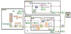
To resolve this issue, first determine if the execution order really needs to be controlled. If it does, the techniques used in Figure 1 may be appropriate. In this example, two single-frame Sequence structures are placed on each side of the While Loops. The wires between the structures create the data dependency.
Click here to see larger image
Data cannot pass through the tunnels out of the Sequence structure on the left until all of its operations have been completed. In particular, the write local variable operations must occur before the data can propagate through the tunnels. Similarly, the While Loops cannot begin executing until they have received data on their inputs. The lower loop actually uses the input data while the connection to the upper loop is there only to establish artificial data dependency.
The Shutdown routine on the right cannot run until it receives the outputs from both While Loops. The General Error Handler VI is positioned between the DAQ Loop and the Shutdown node so that the error handler will run after the DAQ VI completes but before the Shutdown node starts.
It�s possible to present the operations of Figure 1 as a Stacked Sequence structure. But this approach requires sequence local terminals to pass data between frames, and only one frame is completely visible at a time. A three-frame Flat Sequence is another option. All frames are simultaneously visible, and because artificial data dependency is not required, this implementation
is preferred.
To optimize data flow, avoid local and global variables. Use shift registers instead. In LabVIEW, shift registers are terminals on looping structure borders that shift data between loop iterations. Unlike variables, shift registers do not create copies of their data when read, improving their efficiency.
As an alternative to Sequence structures, consider using looped Case structures. If instead, Sequence structures are used, the order in which they are executed depends on their frame numbers. A Case structure embedded within a loop can be controlled programmatically, providing variable execution order.
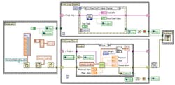
Figure 2 shows the looped Case structure operating as a flexible sequencer in a Classic State Machine design. “The Classic State Machine� consists of a looped Case structure with an enumerated data type for the case selector and a shift register for passing the next case selection between loop iterations. The cases are intuitively labeled based on the text items of the enumerated data type instead of integers. This eliminates the free labels within each case. Also, the Classic State Machine programmatically selects the next case, based on an operation performed in the previous case. In this manner, the test sequence is formed dynamically.”
Figure 2. A Flexible Sequencer Based on a Classic State Machine Design
Click here to see larger image
Why is so much of a chapter on block diagrams devoted to comparisons of different design approaches and structures? The reason is that if you have a wide range of tools with which to address a particular application, you can choose the ones that best accommodate your style objectives. If all your designs used only one type of loop or used Sequence structures instead of looped Case structures, the resulting VI and subVI diagrams would be more complex and less functional and expandable than necessary.
Remember that style, as Mr. Blume defines it, also relates to efficiency. So, there�s a good chance that a messy block diagram will execute more slowly or less efficiently as well as be harder to understand and maintain than one with better style.
One of National Instruments� long-established slogans is, “The software is the instrument.” Well, in LabVIEW, the VIs and subVIs are the software. The block diagram appearance relates directly to how clearly the designer understood the application requirements. Appearance also is a good indication of the difficulties that might be faced should changes be required in the future.
Data Structures
Even inexperienced programmers and engineers will recognize data types such as Boolean, 8-b unsigned integer, single-precision floating-point, matrix, and string. Data constructs are data sets, such as clusters and arrays, which use the basic data types. Data structures are the data types and constructs used by an application.
Chapter 6, Data Structures, opens with these definitions followed by very useful tables of controls, data types, and the relationships among controls and data types. The items are listed in approximate order of increasing complexity.
A particular type of control is compatible with a number of data types. This means that by your choice of control, you are defining the data types you will use. For example, what are the implications of the ways you might handle data entry? The most general approach is to provide a string control into which the user can enter a string of alphanumeric characters.
This also is the most uncontrolled method. Indeed, the user can enter anything. If you really need to cope with a wide range of alphanumeric characters, you will have to provide an error routine that detects invalid entries such as punctuation marks. In most applications, the type of entry can be narrowed to only numeric or only alpha, or best of all, to only a few items comprising a range of choices.
The lists of controls and data types are intended to help you choose the simplest control that will do the job, avoiding the problems involved with more flexible controls such as strings. Either ring or enum structures present a limited number of entry choices. In most instances, it would be very difficult to know which control type the developer had used. Mr. Blume recommends enums for maximum readability within the VI diagram.
For example, when an enum is wired to the selector terminal of a Case structure, the text selections appear in the Case structure�s selector area. This is much more useful to a developer than a ring�s range of numbers to which the text strings are mapped.
Enums and rings are discussed in some detail. “However, there are a few exceptions where a ring control must be used�. Use a ring control when the text labels map to nonsequential, negative, or fractional values or if localization is an issue. Also, use a ring control when creating an instrument driver or developer toolset intended for international distribution.”
The comment about mapping is easy to understand because text labels associated with enums always map to a list of unsigned integers starting at zero. So, if a different mapping is required, you must use a ring. And, it turns out that because the text within the text ring is a symbolic mapping to the integer list, text ring controls are translated by foreign language versions of LabVIEW. Enum text is not. This text remains in the native language of the LabVIEW version in which it was created.
Data structures can be made very complicated. LabVIEW supports arrays, clusters, clusters of arrays, arrays of clusters, clusters of arrays of clusters, and so on. The number of applications that actually would benefit from such structures decreases rapidly with increasing complexity. Nevertheless, nested data structures are useful for organizing complex data or mixes of data in a hierarchical manner.
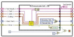
Clusters and arrays are two primary means of organizing data, and their use will greatly influence the appearance of a block diagram. Consider the Steering Column Test VI shown in Figure 3. UUT input data includes the test date, name of car company, name of model, the model year, whether it is a production or development test, the type of test being run, and the test specification reference.
Click here to see larger image
Five motion parameters are developed based on the specification, further user input, and the UUT data. From these values and the measured steering-column performance, an additional six values are calculated that are used in the Generate Report VI and saved. The VIs have so many inputs and outputs and parameter terminals that even the maximum 28-terminal VI layout is not adequate.
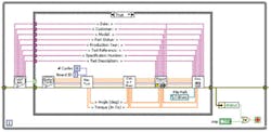
Grouping similar kinds of data into clusters solves the problem. In this example, four separate clusters account for the UUT input data, the motion parameters, torque vs. angle data, and statistics. The simplified diagram appears in Figure 4.
by Grouping Related Signals in Clusters
Click here to see larger image
Arrays always contain only one data type. The elements of an array are distinguishable only by their position in the array. Otherwise, they are identical except that they may have different values.
In contrast, a cluster can group different data types. It is the developer�s responsibility to apply clusters to groups of data that are closely related, such as the items required to define the car being tested and the test being run. Were dissimilar things such as the car model and a torque statistic to be grouped in a cluster, it would be almost impossible to understand what Figure 4 accomplished without reverting back to the lower level view of Figure 3.
Having established one or more clusters, they must be saved as type definitions or strict type definitions. Applying the type definition for every instance of the cluster ensures that any changes will appear everywhere the cluster is used. Also, to access or replace cluster elements, the Bundle and Unbundle By Name functions are preferred to the less rigorous Bundle and Unbundle. Bundle By Name provides terminal labels on the VI diagram that improve readability and maintenance.
Summary
It can be difficult to identify why one person has been more successful than another in performing a given activity. Many factors can be responsible, but the process becomes much easier if you start with a known-good reference.
The LabVIEW Style Book begins in exactly this way. Three VIs are presented for comparison: the Meticulous VI, the Nested VI, and the Spaghetti VI. Even readers with no programming experience can see at a glance that the Spaghetti VI, as the name implies, is a mess of tangled wires, forward and backward data flow, and a wide range of icons and notation. It�s easy to see that this is not the way to go.
The Meticulous VI and Nested VI are obviously much better organized and understandable. Choosing between them requires a deeper understanding of LabVIEW. VI development suggestions are given throughout TheLabVIEW Style Book that will help you produce readable, functional, and maintainable programs. You can choose simply to accept the rules as given or understand the reason for the rule, which usually is discussed in depth.
Because of the large number of considerations brought together under the term style, this book may not be for everyone. If you have little LabVIEW experience, your fastest route to a usable VI is to stick with Express VIs and the dynamic data type. Dynamic is a universal data type designed especially for novice developers. With dynamic data, you don�t have to worry about types, storage, or type conversion: It�s all done automatically.
Similarly, variant is a self-describing data type that stores information in a generic format. It allows a data source to provide any type of data to a destination that can decode and use it. However, variant is used by advanced developers where maximum flexibility is required.
Of course, there is a price to pay for this convenience. Style suffers with reduced memory and processor efficiency, and additional encoding and decoding may be required in related applications.
For more serious programmers, the book provides the balance you need to make informed choices. No two developers will produce exactly the same solution to a given problem. That�s simply the nature of innovation within an environment as broad as LabVIEW. On the other hand, if programmers establish consistent conventions and are mindful of the implications of their choices, equally elegant solutions should result.
FOR MORE INFORMATION
on The LabVIEW Style Book
www.rsleads.com/708ee-176
August 2007


