Performing EMC tests on large electronic equipment can be problematic especially if the EUTs can’t be moved. It doesn’t matter how large a test chamber may be, some EUTs must be tested in situ. Here are a few examples.
• Ares I Rocket: a 308-ft tall x 18-ft dia unit that can be launched but not moved after assembly: Multiple power, control, and signal cables run the length of the system to various redundant analog and digital sensors and equipment located at its top and bottom.
• New York City Hospital magnetic field susceptibility problem: This was caused by an underground subway passing adjacent to a neurosurgical operating room and turned out to be magnetic loop coupling from improper installation.
• RF emissions problems from an induction furnace used for annealing a moving 60-inch web of sheet steel: This turned out to be a radiation hazard issue.
• The tunnel radio system interference within Boston’s Big Dig: This was an intermodulation problem.
• An Ohio coal-fired power plant control system susceptibility problem resulting from an instrumentation upgrade from vacuum tubes to solid state: One volt of noise on a 250-V plate supply is not nearly as much of a problem as it is on a 5-V logic device.
• Interference from an unattended telephone switching center in Iowa to local TV reception in a three-block radius when it was changed over from code switches to a computer-controlled digital switching system: More subscriber features, more subscriber problems.
In all of these cases, the system being tested is the combination of the installed EUT and its surrounding RF environment/equipment. Because the installed RF environment is part of the system, tests and examinations have to be done in situ; that is, tested in place. This often happens with large-scale system installations and generally is accompanied by the unexpected.
Everywhere you want to set up an antenna there is a wall, a column, a power line, a piece of equipment, and high-level RF signals that exceed the spec limit for the test. Plus in an industrial environment, the RF ambient always is changing, which makes it extremely difficult to determine what’s the EUT and what’s ambient.
For really big test samples, antennas may have to be hoisted up the side of the EUT using nylon rope, or the test engineer may have to perform the testing from the bucket of a cherry picker.
On-site testing is similar because it takes place where the EUT is located, but that does not imply that the EUT can’t be moved. Moving things around changes the system configuration.
Even though all components, subassemblies, and equipment have met their respective EMC requirements, it does not mean that the final assembly will. If it does, great. But that does not, in turn, mean that after installation the total system including the surroundings will be compatible. That’s the reason for doing in situ tests.
Measurement Objectives
Most of the time even a large-scale system is prototyped and determined to be sound before it or an identical system is delivered and built in its operational location. As a result, the installed system is nearly complete, and at that time in the design cycle it is very difficult to make changes. Nevertheless, field fixes usually are not as costly as design changes.
In situ measurements typically are done in response to a problem that shows up after installation because of unforeseen interaction with the RF environment. But that doesn’t have to be the case. Regardless, before testing starts, it’s necessary to establish the purpose of the measurements:
• Does the installed system cause interference to surrounding systems?
• Is the installed system susceptible to some ambient EM signal?
• Is this test a qualification test?
• Are radiated emissions levels a possible personnel RF hazard?
• Does an ESD or lightning transient upset the operation of the equipment?
The purpose determines the procedure, the test equipment, and the support required.
As a general rule, when the testing is done in situ, it’s not necessary to test the system and all I/O with every possible procedure, only those that may be a problem and only in its typical operating configuration. However, the test arrangement chosen must be configured to produce the maximum emissions possible during operation.
The overall system must be self compatible. It must operate and do its intended function in the installed configuration. Unless the system must be tested to and meet specific radiated susceptibility requirements in the installed configuration, the EUT susceptibility is essentially determined by the fact that it does or does not function properly within the environment. Unfortunately, demonstrating compatibility with the ambient RF environment does not establish an EMC margin of safety.
Most of the time, large installed systems will be required to meet commercial rather than military EMC specifications. For that reason, the procedures from ANSI C63.4 and IEEE/ANSI-STD-139 are not only appropriate, but they also will provide you with a great deal more information about in situ testing.
Minimum Tests to Perform
The FCC’s requirements for Part 15 Class A Commercial Equipment point out which tests are considered the most important. The rules state that:
• Equipment must be installed and used in accordance with the instruction manual.
• FCC limits for conducted and radiated emissions provide reasonable protection against harmful interference, but there are no guarantees.
• Operation of the equipment in a residential area may cause harmful interference. Remember the limits do not guarantee that it won’t. However, harmful interference is not permitted. If it happens, the user of the equipment must incur the expense to correct any interference, not the manufacturer.
• Equipment must accept any interference received, including that which may cause undesired operation.
From the manufacturer’s point of view, all they must do is verify that the EUT meets the appropriate FCC conducted and radiated emissions requirements and then let the user beware.
Just to set the record straight, the user of the equipment probably did not design or manufacture the EUT, and if it is a large-scale system, such as one built on-site, the user probably did not install it either. This means the user does not have a clue about how to correct any of the problems. So if the manufacturer wants to stay out of trouble with the FCC and get paid by the user, the EUT best not interfere with surrounding equipment, and it needs to operate reliably in the local ambient RF environment.
Many different tests often are run to assure continued compliance for EUTs that can be moved to a new location anywhere at any time. For a permanently located large-scale system, the number of tests can be substantially reduced and still provide reasonable assurance that, at the time of the test, it will function properly at its installed location and not upset other colocated equipment.
In situ testing is used to solve problems in the field, not as a substitute for laboratory EMC testing in an RF controlled environment. If EMC tests can be done in a laboratory, then that should take priority. In situ test results apply only to that installation at that time. If multiple installations are tested and similar results are obtained, it may be possible to infer that other installations will perform in a similar way.
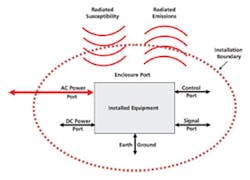
As illustrated in Figure 1, a minimum of four tests generally is needed to verify and troubleshoot a large-scale system:
• Conducted emissions on AC power, control, and signal leads
• Radiated emissions from the EUT
• Conducted susceptibility/immunity on AC power, control, and signal leads (AM and transients on all leads that cross the environment boundary)
• Radiated susceptibility/immunity at the EUT
All of these tests are difficult to do in an uncontrolled RF environment. Some, however, are a lot more difficult to perform in situ than others. Radiated susceptibility is especially difficult because the test may upset the operation of other collocated equipment.
Detailed test procedures and safety precautions for these various EMC tests are contained in the appropriate test specifications for the EUT, such as FCC Part 15 or Part 18, MIL-STD-461, ANSI C63.4, EN 55011, EN 55022, or IEC 61000-4-2, -4, -6.
Performing Measurements
For a large-scale system, a minimum of two people is required to perform the tests. Both should be equipped with hand-held transceivers or sound-powered telephones. The choice is determined by the sensitivity of the surrounding equipment. Two-way communications are needed because some large-scale systems may be really large and have portions on more than one floor or on opposite sides of a wall, or the tests may be made at the boundary of the facility.
One person familiar with the operation of the EUT should set up and monitor its performance; the other performs the EMC tests. In the event of an anomaly, the monitoring person communicates with the test person to stop the test.
To minimize the disturbance of the electric field during both the radiated emissions and the susceptibility tests, the person operating and monitoring the performance of the EUT should stay in the same place if possible. In no case should the operator or test engineer stand directly between the antennas and the EUT.
During the emissions tests, the EUT is configured in the normal operating mode that will produce the greatest emissions levels for the test being performed. For example, if the maintenance mode draws the most current and produces the highest emissions levels, use that mode rather than its regular functional mode. Do not reconfigure the EUT just to produce the greatest emissions levels if it is not expected to be operated in that mode.
The EUT should be inspected to assure that it is installed in accordance with the manufacturer’s instructions. IEC 61000-5-1 on installation and mitigation guidelines is a good document to review before doing this inspection. There’s no reason to penalize the EUT for an emissions problem if the system wasn’t properly grounded or someone forgot to tighten the screws around an access panel.
During the inspection, check out the power input and decide if it will be possible to install power line impedance stabilization networks (PLISN) or if some other approach must be used. Likewise, make notes about where the likely areas of maximum emissions/susceptibility coupling may be located.
Ambient EM Noise Levels
For each emissions test, the RF ambient levels should be measured. Ideally, with the EUT turned OFF, the levels should be no greater than the required specification limit and preferably 6 dB or more below the limit. By comparing the measurements with the EUT ON and OFF, it’s possible in most cases to determine which emissions are ambient and which are from the EUT. Unfortunately, it becomes much more difficult in a high-level RF environment or one in which the levels are continuously varying because the ambient masks the emissions from the EUT.
Ambient measurements differ somewhat depending on the type of test.
Conducted RF Ambient
These measurements are done on power, control, and signal leads and, unless they are controlled, directly affect the radiated emissions from the EUT. Power-lead emissions are required to meet the FCC requirements, and they potentially are the most difficult to separate from the ambient. Ideally, a noninductive resistive load that draws the same current within ±25% as the EUT should be substituted for or wired in parallel with the EUT and measured while the EUT is OFF to determine the ambient levels. Power, control, and signal leads should be tested to as high a frequency as practical because these measurements are used to determine the source of the radiated emissions.
Radiated RF Ambient
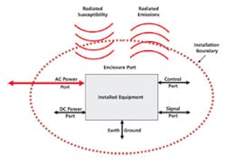
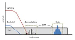
This measurement is straightforward, but as illustrated in Figure 2, the radiated ambient can be quite complex. At each antenna location where the EUT is measured, perform a scan with the EUT OFF to determine the radiated RF ambient both before and after the EUT measurement. Having both the before and after RF ambient measurements helps to reduce the problems associated with a changing RF ambient. If these levels are high, the tests may have to be performed during the night or on weekends when the ambient is lower.
Versions A, B, and C of MIL-STD-461 use a correlation procedure to detect the EUT emissions in the presence of a high-level RF ambient. In lieu of a correlation procedure, it is necessary to measure the EUT at a close distance where the EUT emissions exceed those of the ambient and extrapolate the levels to the specification limit distance.
Keep in mind that ground is not ground. It often is a common-impedance coupling path, a return for common-mode currents, or a reference for someone’s antenna. Plus, if it is not stable, then RF changes in the ground system will result in noise being coupled into or out of the system.
Most of the measurements are made with respect to ground, and any ground system noise will add to the measurements. Consequently, it is important to know the magnitude of any RF noise on the ground system. This can be determined using a current probe around the ground lead.
Overview of Emissions Tests
Emissions tests are performed to assure that the EUT does not interfere with the operation of other collocated equipment. The entire frequency range should be continuously swept using a slow enough sweep time to assure that all emissions and emissions frequencies are measured.
Most modern measurement receivers will tell you if the setup is calibrated and provide a valid measurement but not whether the sweep is slow enough to allow the EUT enough time to complete an operational cycle. The larger the EUT, the more time it takes for it to complete an operational cycle.
During that time, signals come and go, and their amplitudes vary. If the receiver or spectrum analyzer has a peak-hold function, free-running multiple scans can be used to increase the probably of emissions intercept. Unfortunately, this also captures more RF ambient. Sometimes, it takes luck to have the receiver tuned to an emissions frequency at precisely the time it occurs. As a result, a system that appears to have passed all tests may occasionally have undetected failures that show up later during use.
Emissions test specifications may call out CISPR quasi-peak or true peak detectors. True peak is capable of detecting and measuring short-duration transients. This allows the emissions effect on digital devices to be analyzed. Quasi-peak detectors use weighting circuitry to assess the listener’s perception of interference on 1930s AM radio broadcasts. Not all measurement receivers or spectrum analyzers have a CISPR quasi-peak detector. If the EUT meets the requirement using true peak detection, it will meet the requirement using quasi-peak.
Whenever possible, while performing conducted and radiated emissions measurements, use a receiver or spectrum analyzer with an audio output to listen to the detected RF. It is amazing how much information is contained in the interference modulation.
Switched-mode power supplies have a unique modulation signature whether at baseband or at 500 MHz. By listening to the audio, it is possible to tell where the emissions originate. Computer-controlled spectrum analyzers cannot make these determinations.
Part 2
Part 2 of this article, which will appear in the December issue of EE, provides a brief overview of the four primary tests: conducted emissions from AC power, control, and signal leads; radiated emissions from the EUT; conducted susceptibility on AC power, control, and signal leads; and radiated susceptibility of the EUT. It also will focus on issues that must be addressed when performing these tests on a permanently installed system and include comments about the report contents.


