Part 1 of this article appeared in the November issue of EE.
Ideally, most EMC tests are done at an EMC test facility with the EUT in a shielded enclosure. Sometimes, though, the EUT just can’t be moved because it must be tested in its surrounding RF environment or in situ. But regardless of location, there are four primary tests to be performed: conducted emissions from AC power, control, and signal leads; radiated emissions from the EUT; conducted susceptibility on AC power, control, and signal leads; and radiated susceptibility of the EUT.
Conducted Emissions
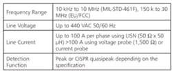
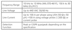
A commercial EUT must comply with this FCC test requirement (Table 1). The test procedure and limit are determined by either FCC Part 15 (EN55022) or Part 18 (EN55011). The compliance test uses the ANSI/CISPR test procedure and is required for FCC qualification for power leads. Except for minor differences in instrumentation and setup, the MIL-STD-461 test procedure is very similar.
If this is a qualification test, a line impedance stabilization network (LISN) of 50 ? x 50 µH is appropriate for both MIL-STD-461F and EU/FCC tests, assuming that the LISN is capable of handling the EUT current.
The LISN essentially is a Pi filter with a sensing resistor in one leg. It provides a standardized power-line impedance, decouples the EUT from the power system, and improves test repeatability for multiple locations.
If a LISN can’t be used, the alternative is a voltage or current probe. The choice depends on the specification and whether power can be removed easily from the EUT. If the system can’t be turned OFF, then a voltage or current probe test is required.
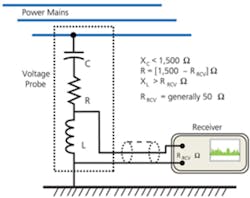
A voltage probe simply is an RC blocking network with an inductor, sized to provide a total resistance of 1,500 ? between the line and ground (Figure 1). Because of impedance variations with frequency, calibration is required. A voltage probe is not used in conjunction with a LISN.
Because the limits in most of today’s standards are given in terms of voltage, if a current probe is used, the line impedance is assumed to be 50 ?, and the voltage is calculated. Remember, just because the line impedance is assumed to be 50 ? does not make it so. There may be significant errors because of impedance variations from conduit, buried or overhead wiring, or stiffness of the power source.
If this is an interference or susceptibility issue, then determining the relative emissions levels on the power, control, and signal leads generally is more important than knowing the absolute value. The current probe does a great job with this. Just clamp the probe around the entire power cable to measure common-mode RF currents on the cable. Nothing needs to be turned OFF, disconnected, inserted, or modified.
The conducted emissions test principally measures common-mode emissions on leads. This means that the grounding system of the measurement receiver can be an element in the EUT measurement circuit. Although it may not be necessary, the power for the measurement receiver should be isolated from that of the EUT. This can be accomplished by powering the receiver using an isolation transformer, a separate power phase, or a DC-powered measurement receiver. This same recommendation holds for radiated emissions measurements.
Radiated Electric Field Emissions
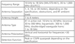
A commercial EUT must comply with this FCC test requirement (Table 2). The test procedure and limit are determined by either FCC Part 15 (EN55022) or Part 18 (EN55011). The compliance test uses the ANSI/CISPR test procedure. Except for some minor differences in instrumentation and setup, the MIL-STD-461 test procedure is very similar.
In the laboratory, this test normally is performed with the EUT located on a turntable. But that is not possible with a permanently installed EUT so multiple antenna locations are used instead.
From where the measurement antenna is located, if the antenna is assumed to have a 45-degree beam width and that angle encompasses the entire side of the EUT, then make measurements in the center of each side. If the EUT is large, take more measurements to assure that the worst-case emissions have been measured.
If there are a large number of antenna locations to be tested, the time can be reduced by performing the scans with a polarization angle of 45 degrees. If emissions are found, then determine if the worst case is vertical or horizontal or simply add 3 dB to the value.
Although it would be preferable to use a standard test measurement distance, the antenna separation distances from the EUT boundary may vary because of obstacles. Under these conditions, the data must be normalized to a standard measurement distance before worst-case emissions levels vs. azimuth can be established. These same obstructions also introduce measurement errors because of antenna loading and reflections.
Susceptibility Tests
Susceptibility tests are performed to assure that the EUT will function properly in its installed RF environment. Ambient RF signals may disrupt or degrade the operation of the equipment. The entire frequency range should be continuously swept using a sweep time slow enough to assure that all susceptibility frequencies are measured.
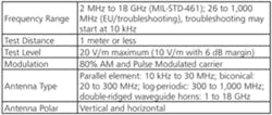
The radiated susceptibility test levels typically are produced using a signal generator and RF power amplifier in conjunction with an antenna that is usable over the test-frequency range. A test distance such as one meter is recommended to minimize the RF exposure levels to which collocated equipment is subjected.
Use the E-field probe or a receive antenna and a spectrum analyzer to monitor the RF exposure levels at the EUT. If the 20-V/m level cannot be obtained at the recommended test distance, move the transmit antenna closer to the EUT. Do not increase transmit power unless absolutely necessary, and don’t get close to the antenna while transmitting.
The performance of the EUT should be monitored for any degradation in performance. If performance degradation occurs, stop the frequency scan, reduce the level until the performance returns to normal, and increase the RF level until the degradation recurs. Record this level.
To reduce the test time for a large number of antenna locations, perform the scans with a 45-degree polarization angle. If a susceptibility is found, determine if the worst case is vertical or horizontal.
From the susceptibility perspective, external radiated energy results in conducted currents being induced into wires and cables that are outside the test sample envelope. But because it takes such large radiated signals to produce the same signal levels in the conducted susceptibility frequency range, conducted susceptibility tests are performed first, and those problems are solved before continuing on to radiated susceptibility.
Modulation
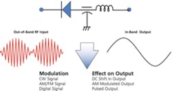
Susceptibility test signals should be modulated. Most ambient RF signals are used to convey information, and as a result, they are modulated. The RF carrier may bring the RF energy to the system, but it usually is RF demodulation or audio rectification by nonlinear devices that causes the susceptibility. Very seldom is there a susceptibility problem caused by a continuous wave (CW) signal.
Figure 2 illustrates the problem. Depending on the specification, the required modulation typically is 50% or 80% AM/pulse at 1 kHz. This generally is because signal generators have this built in. If the test is being performed because the EUT has a susceptibility problem, use 100% AM/pulse modulation for troubleshooting.
During the susceptibility tests, operate the EUT in the normal operating mode that will result in its most susceptible condition for the test being performed. For example, if the maintenance mode exposes sensitive circuits and has the greatest susceptibility, use that mode rather than its regular functional mode. If you are willing to accept the EUT’s susceptibility outside its regular functional mode, then use the regular functional mode for the test if there are no safety issues. Do not reconfigure the EUT into a mode that is not a normal operating mode just to make it more susceptible.
The EUT’s susceptibility profile also changes during an operational cycle. During susceptibility testing, the sweep must be slow enough to allow the EUT time to complete an operational cycle. During that time, different circuits are activated which may have decidedly different susceptibility characteristics. MIL-STD-461F uses a dwell time of 3 seconds per frequency step. Once again, it may take luck to have the signal generator tuned to a susceptibility frequency at precisely the time that circuit turns ON.
Conducted Susceptibility
Although the EU and military requirements include conducted susceptibility, the FCC does not have a corresponding requirement. The test procedure for doing susceptibility troubleshooting depends on the characteristic of the EUT’s susceptibility.
Susceptibility Requirements
The test should correspond to the EUT’s susceptibility problem being evaluated. This typically will be to a modulated RF carrier or to transients, usually on the power line. Conducted susceptibility procedures from IEC 61000-4-4, IEC 61000-4-6 (Table 3), or MIL-STD-461F are appropriate.
For transient susceptibility, the electrical fast transient (EFT) test IEC 61000-4-4, or MIL-STD-461F CS106 can be used as an alternative. The choice will depend on the nature of the test (Table 4).
61000-4-4 Test
The EU and MIL-STD-461 EFT tests require specialized equipment. Provided it is not a qualification test, it is possible to perform some transient testing using the MIL-STD-461C RS06 chattering relay test or an ESD gun. These two procedures use less expensive equipment.
Interference problems always start out somewhere as conducted energy and end up the same way. For this reason, performing conducted susceptibility tests on all power control and signal leads does a reasonable job of simulating a radiated susceptibility test without radiating everything in sight. However, radiated susceptibility testing establishes and immerses the EUT in a known electric field which penetrates through cabinets and cable shields and induces currents in system conductors simultaneously; conducted susceptibility does not.
Radiated Electric Field Susceptibility
Susceptibility Requirements
Generalized radiated susceptibility procedures from IEC 61000-4-3 (Table 5) or MIL-STD-461F RS103 are appropriate although they can’t be fully implemented in in situ testing. These procedures also require performing the tests with both vertical and horizontal polarization. This doubles the EUT test time and the time that the neighboring equipment and personnel will be exposed to the RF fields. Test time can be reduced using a 45-degree antenna polarization which results in a lower 3-dB level than vertical or horizontal.
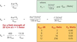
Because the EUT is not in a shielded enclosure, both the system’s operator and the test engineer are located in the RF susceptibility field. For that reason, a maximum test level of 20 V/m is suggested, based on the FCC’s RF exposure limit for the general population/uncontrolled exposure of 0.2 mW/cm2 in the 30- to 300-MHz frequency range where the human body is resonant.
This equates to a far-field RF field-strength level of 27.5 V/m. This is a fairly strong field, and cables act as good antennas so avoid upsetting nearby equipment. Figure 3 shows the relationship of transmit power, antenna gain, and field strength.
Measurement Reporting
The various commercial and military EMC test standards provide guidance on what information should be included in an EMC test report. Unfortunately, most of these assume that the tests were performed in an EMC laboratory. In situ measurements are somewhat different because the test setup is take-what-you-get.
The MIL-STD-461F report format document Data Item Description: DI-EMCS-80200B provides a good example of the typical information required in an EMC test report:
Administrative Data
a. Contract number
b. Authentication and certification of performance of the tests
c. Disposition of the EUT
d. Description of the EUT, including its function, characteristics, intended installation, actual cable types, and electrical current usage on each power input line
e. List of tests performed with pass/fail indications
f. Approved deviations from contractual test procedures or limits previously authorized
g. Identification of nondevelopmental items and government- furnished equipment that is part of the EUT
h. Traceability of test equipment calibration
i. Reference to the approved EMI test procedure
Detailed Results
Prepare a separate appendix for each test. If deviations from an approved test procedure occurred during the test program, provide an additional appendix with the as-run procedures showing all red lines and procuring activity concurrence. Also develop a separate appendix for log sheets. Each test appendix shall contain the following data:
a. Test equipment nomenclature, serial numbers, version of software used, and calibration due date
b. Photographs or diagrams of the test setup and EUT with identification
c. Transfer impedance of current probes
d. Antenna factors
e. Impedance values of LISN
f. Identification of suppression devices used to meet the contractual requirements, including schematics, performance data, and drawings
g. Sample calculations, such as conversions of measured levels for comparison against the applicable limit
h. The ambient radiated and conducted electromagnetic emissions profile of the test facility when necessary
i. Data as specified in the data-presentation sections of the individual test procedures of MIL-STD-461
j. Scan speeds
k. Measurement receiver bandwidths
l. Antenna polarization
m. Power-line voltages, frequencies, and power factor
n. Low-noise amplifier compression points
o. Thresholds of susceptibility determined
Conclusions and Recommendations
Conclusions and recommendations shall include results of the tests in brief narrative form, a discussion of any remedial actions already initiated, and any proposed corrective measures required to assure compliance of the equipment or subsystem with the contractual EMI requirements.
Additions for In Situ Test Reports
For in situ tests, add the following information to the corresponding sections:
Administrative Data
•?Reasons for carrying out the test
•?The basic test standards used to evaluate the EUT
•?Unusual environmental conditions that might affect the measurements
Detailed Results
Prepare a separate appendix for the physical inspection. The FCC requires that the EUT be installed in accordance with the manufacturer’s instructions. The physical inspection should cover the following:
•?Condition of the EUT
•?Grounding method and location
•?Bonding/corrosion
•?Shielding used, attachment method, and condition
•?Filters and their installation
•?Cable terminations/pigtails
•?Diagram of the EUT layout with respect to the facility and locations where tests were done
•?Photographs including the boundaries of the equipment to be tested
Since there may be major deviations from laboratory setup, the test appendix should describe:
•?Operator positions
•?EUT operating modes
•?Susceptibility criteria if applicable
•?EUT boundaries
•?Start-up/shutdown sequences
•?Antenna and other sensor positions
•?Power, control, and signal leads tested
Conclusion
In situ measurements are difficult, time-consuming, and expensive. Characteristically, some EMC problems show up after installation because of unforeseen interference with the ambient RF environment. As a result, organizations now use a 9-dB safety margin for large-scale systems to mitigate EMC problems after installation.
