Ensuring EMC for military applications is challenging. On the one hand, maneuvers should be undertaken without the enemy’s knowledge, so radiated emissions have to be controlled to ensure secure communications. At the other extreme, the electromagnetic environment to which munitions are subjected must not inadvertently activate them. Guaranteeing adequate immunity to high RF fields for electrically initiated ordnance is a critical safety issue.
These kinds of emissions and susceptibility concerns have benefited from concerted and well-organized research for many years, especially regarding the safe storage and handling of ordnance aboard Navy ships. The Hazards of Electromagnetic Radiation to Ordnance (HERO) program is the U.S. Navy’s comprehensive approach to mitigating the inherent incompatibility of RF emissions and electrically initiated explosives.
Figure 1. Carrier Flight Deck With Ordnance Exposed to Multiple RF Sources
Courtesy of Naval Sea Systems Command
Land-based services can increase RF immunity by providing a greater distance between the ordnance stockpiles and emissions sources. As shown in Figure 1, this isn’t practical aboard a ship or inside an airplane. For that reason, the Navy has taken the lead in developing practical EMC guidelines that support safe munitions deployment near personnel.
The HERO Program
The Navy’s HERO program was described in detail in an issue of the Naval Sea Systems Command publication Leading Edge that focused on solving the challenges of electromagnetic environmental effects (E3).1 The three main elements are certification testing, surveys, and guidance.
Testing
All weapons classified as electrically initiated devices (EIDs) must obtain HERO certification before they can be issued a national stock number or Navy ammunition logistic code. Weapons cannot be deployed to the fleet for use unless they have the requisite stock number or code.
Testing follows MIL-STD-464 DoD Interface Standard for Systems Electromagnetic Effects Requirements and determines the item’s susceptibility to the operational electromagnetic environment (EME). If the weapon is susceptible, the maximum allowable environment (MAE) is established. The term EME includes the possible RF exposure at all stages from stockpile to safe separation.
Survey
Having determined the MAE for a weapon, the next step is to compare that level to the wide range of EMEs found in practice. As explained in the article, “With many ordnance items, the host platform or system—airframes, bomb racks, dispensers, or interface cables—varies as [the ordnance] progresses through the stockpile-to-safe-separation sequence, and these differences can have a pronounced influence on the amount of RF coupling.
“Furthermore, it can be expected that the EME associated with each will be quite different and, therefore, must be fully understood. The test EME should simulate the specified operational EME to the extent necessary to stimulate maximum EID and firing circuit responses…. Thus, it becomes immediately obvious that the HERO survey process is critical to the certification testing process, as this is where operational EMEs are characterized, and specific ordnance configurations and procedures are identified.”1
Guidance
Information gathered during testing and surveys is disseminated via several means. A site-specific emissions control (EMCON) bill helps to minimize radar and communications systems restrictions as well as improve efficient use of ordnance storage areas. It also assists by providing guidance for joint and coalition forces operations.
“For the Navy HERO program, guidance comes in other forms, including technical manuals, instructions, shore facility site approval analyses, shipboard system certifications, and general fleet guidance to support naval operations. Electromagnetic Radiations Hazards (Hazards to Ordnance) is the Navy HERO program technical manual…. The …[manual’s] datasheets provide HERO classifications… and contain the Navy’s susceptibility data as a result of HERO testing. Another document… is Design Principles and Practices for Controlling Hazards of Electromagnetic Radiation to Ordnance [and is the] HERO design guide.”1
Survey Techniques
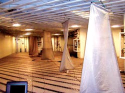
Two approaches have been used to characterize ordnance storage spaces on ships. The first, as described in an E3-related article in Leading Edge, “is to physically stir the energy within a space using large, electrically conductive tuner assemblies while simultaneously measuring the resultant electric field intensity.”2
Figure 2. Physical Mode Stirring Setup Aboard USNS Sacagawea
Courtesy of Naval Sea Systems Command
Although a storage area may be relatively large, fields don’t propagate as they would in free space. Generally, the spaces are irregularly shaped chambers constructed from conductive material, so RF energy reflects off the walls multiple times, combining to increase the maximum intensity. Figure 2 shows measurements being performed onboard USNS Sacagawea.
Physical stirring increases the random nature of the electric field. “Complex [cavities are] characterized by a chaotic electric field standing-wave pattern of maximums and minimums whose locations are very sensitive to small changes in boundary conditions, such as occur from changes in physical structure…frequency…loading…temperature, over a period of time…. A deterministic analysis, either by measurement or by modeling/simulation of such chaotic fields, is neither practical nor useful as substantial changes are caused by perturbations. Useful descriptions must be statistical in nature and independent of details.”2
If a sufficiently large number of modes are excited within a reverberant chamber, the central limit theory of statistics can be applied. This means that the electric field strength will follow aNevertheless, running a test as shown in Figure 2 isn’t practical in many circumstances and always is inconvenient and time-consuming. A second type of test takes advantage of overmoding naturally occurring within this type of cavity. Boundary condition changes caused by personnel and material motion as well as a hatch or door opening and closing generate additional modes.
In this approach, a 0-dBm transmitter is mounted at one end of a 1-meter pole and an oppositely directed receiver at the other. To perform this test, an operator walks around in the cavity of interest, recording the received power level at many locations and orientations. The two methods have been proven to be equivalent, allowing the much more convenient second technique to be used to characterize spaces that the former method could not.
As explained by Tait and Slocum, “…The Electromagnetic and Sensor Systems Department engineers from Naval Surface Warfare Center (NSWC) Dahlgren have measured the electromagnetic environments in more than 60 below-deck compartments in several ships in port at Naval Station Norfolk…. It was found that these spaces can be characterized as complex reverberant cavities that can sustain fairly high maximum electric field levels over the 200-MHz to 10-GHz frequency range.
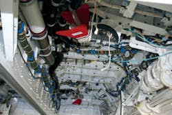
“Typical maximum cavity calibration factors range from 1-10 V/m/Figure 3. Fighter Aircraft Left-Side Main Weapons Bay
Courtesy of NSWC Dahlgren and IEEE
Aircraft Weapons Bay Survey
A 2009 IEEE paper by Gregory Tait and Michael Hatfield at NSWC Dahlgren and colleagues at the Aeronautical Systems Center at Wright-Patterson AFB discussed work done to determine the EME within a fighter aircraft main weapons bay (MWB) shown in Figure 3.3 Walking around inside the cavity wasn’t possible, so instead eight separate pairs of transmitter/receiver locations were monitored.
Not surprisingly, given the relatively small size of the cavity, mode stirring improved with increasing frequency. Nevertheless, the maximum electric field strength closely followed aA further complication in this survey was the presence of a 1-kW flight termination transponder located within the MWB. Because of the possibility that this 1-kW pulse would add to the high RF level already existing in the weapons bay, more work was required. “…further electromagnetic vulnerability and HERO assessments are required to ensure safety of flight for the aircraft and to verify missile immunity when this high-power telemetry module is operated in the MWB.
“…The total field strength at any point within the MWB volume will consist of both direct illumination and multi-path (reverberant) contributions. Due to the proximity of missiles to the telemetry module emitter antenna, the direct illumination component may dominate.”3
RF Leaks
In another example involving complex cavities, the RF leakage from an aircraft carrier control room was investigated. The carrier bridge space was characterized by walking around with a transmitter/receiver combination, and as in similar surveys of ordnance storage areas, the electric field strength was found to follow aBy taking into account cable attenuation, antenna correction factors, and calibration of the tracking generator output power variation, a measured frequency-dependent insertion loss was derived. From this, the average power density in the bridge space could be found.
The bridge-window transmissivity was measured as -8 dB at 2.4 GHz and -6 dB at 5.8 GHz. “…the leaked power [through the windows] is independent of [the bridge space] volume…. The leaked power does depend strongly on the insertion loss characteristics of the complex cavity through surface area, wall material effective conductivity, frequency, loading, stirring effectiveness, etc.”4
To determine the relative importance of window leakage, several off-hull receiver locations were used to monitor power during the walk-around characterization. One location was 240 meters on the starboard side, and another was 447 meters forward of the carrier bridge window. A 100-mW (20-dBm) CW signal was used for the tests.
The measured 5.8-GHz results from the 447-meter site were adjusted to reflect the approximately 12-dB difference between CW and 802.11b/g modulated signal power. Also, wireless transmitters typically operate with 25 mW, not 100, so an additional 6-dB reduction was made.
“Nevertheless, it is clear that the EMCON specification [of -110 dBmW/m2 at a distance of 1 nautical mile] is exceeded by a margin on the order of 25-30 dB. Hence, further consideration is warranted for off-hull emissions as a result of wireless network transmissions from reverberant below-decks spaces with aperture coupling to the outside environment.”4
Summary
By carefully performing two very different types of tests that had been postulated to be equivalent, personnel at NSWC Dahlgren were able to confirm that indeed they were. This was an important step because it allowed confident use of a very straightforward and fast test method. Further, because the test apparatus is relatively compact, many complex cavities could be investigated that were not well suited to physical mode stirring with conductive tuning mechanisms.
The flexibility of the walk-around test technique has been demonstrated through two specific surveys with very different objectives. One example simply mimics the work done many times to characterize shipboard ordnance storage areas, but this time onboard a fighter aircraft. The measurement technique had to be modified to suit space and time constraints, but the overall method still yielded good results.
In the other example, the walk-around survey established the insertion loss within an aircraft carrier bridge space. With that knowledge, the level of off-hull transmissions from wireless networks, RFID tags, hand-held radios, and telemetry sources could be derived.
References
1. Denham, C.C., “The Department of the Navy’s HERO Program,” Leading Edge, Vol. 7, Issue 1, pp. 68-76.
2. Tait, G.B., and Slocum, M.B., “Complex Cavities: Assessing the Electromagnetic Environment of Below-Deck Spaces in Navy Ships,” Leading Edge, Vol. 7, Issue 1, pp. 62-67.
3. Tait, G.B., et al., “Electromagnetic Complex Cavity Characterization of a Fighter Aircraft Main Weapons Bay,” 2009 IEEE International Symposium on Electromagnetic Compatibility, pp. 208-213.
4. Tait, G.B., et al., “Off-Hull Radio Frequency Emissions From Below-Deck Spaces in Ships,” 2010 IEEE International Symposium on Electromagnetic Compatibility, pp. 875-880.


