As the mobile and portable device industry began evolving, manufacturers were more or less on their own. Consequently, many technologies and interfaces, usually not well defined and often proprietary to component and subsystem vendors, were used. Such fragmentation tends to limit innovation by making it far more difficult to quickly bring out new mobile products with advanced features and higher performance or that deliver improved battery life and smaller form factors at lower costs.
To address these inconsistencies, the Mobile Industry Processor Interface (MIPI) Alliance was formed in 2003. The resulting MIPI standards already are starting to improve interoperability and help minimize many of the challenges faced by the mobile handset developers and manufacturers to deliver more capable high-speed interfaces.
MIPI Technologies
While there are countless design variations, there are four core areas in any mobile phone or portable device design:
- Display Unit: All mobile phones today have one or more displays ranging from 1 to 2 inchesto 10 inches. Thin-film transistor (TFT) is the most common display technology, but other technologies are emerging.
- Camera Unit: Eighty percent of mobile phones today have cameras, ranging from 1 megapixel to 12 megapixels, with higher resolution becoming commonplace.
- Multiple RF Components: All mobile phones today have GSM or CDMA RF chips. In addition, most of the phones are equipped with RF chips for FM radio, Bluetooth, GPRS, Wi-Fi, and GPS. Next-generation phones will add MobileTV and WiMax.
- Peripherals: All mobile phones today have audio components such as a microphone, speaker, or earpiece. In addition, there are keyboard interfaces, touchscreens, accelerometers, extended buses, and much more.
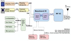
Going a step deeper into these areas, Figure 1 shows how the MIPI standards are replacing the legacy interfaces. Display units interface to the main baseband processor using the display serial interface (DSI). Similarly, camera units connect to the baseband processor using the camera serial interface (CSI). RF chips have a single standard to interface to the baseband processor called DigRF. Lastly, audio peripheral components use the MIPI SlimBus standard.
Figure 1. Mobile Terminal Block Diagram
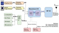
One of the primary roles of MIPI standards is to convert legacy parallel interfaces into modern serial data interfaces. As a result, all MIPI standards are serial data and follow a set of protocol stacks. Figure 2 shows an overview of application areas in a mobile design against the applicable MIPI physical layer and protocol layer standards.
Figure 2. MIPI Technologies Protocol Stack
Source: MIPI Alliance
The physical layer standards include D-PHY, M-PHY, SlimBus, HSI, and DigRF 3G. The protocol layer standards are in yellow and include CSI, DSI, SlimBus, DigRF 3G, and DigRF 4G. The protocol layer standards also incorporate UniPro and HSI at the transportation layer.
For camera applications, the protocol layer currently is CSI-2 with D-PHY as the physical layer. The next-generation CSI-3 will use M-PHY as the physical layer. For display applications, the protocol layer is currently DSI-1 with D-PHY as the physical layer. The next-generation DSI-2 will use M-PHY as the physical layer. The BB-RF interfaces will use DigRF 3G or DigRF 4G with M-PHY as the physical layer.
There are significant advantages to moving to MIPI DSI or CSI, for example. In the case of DSI, the legacy interfaces between a display unit and a baseband processor use 45 to 50 signal connections on the hardware board. By moving to MIPI DSI, the parallel signals are converted to serial, reducing the pin connections to eight to 10. With fewer signal connections, there is less power consumption on the board, less board real estate needed, and lower chip integration cost and time.
The two PHY layers, D-PHY and M-PHY, are expected to coexist for a long time. Both are reusable, scalable physical layers for the various components on a mobile terminal.
First out of the chute, D-PHY differs significantly from many existing mobile interfaces because it can switch between the differential high-speed (HS) and the single-ended low-power (LP) modes in real time depending on the need to transfer large amounts of data or to conserve power to prolong the battery life. The D-PHY interface is capable of operating in simplex or duplex configurations with a single data lane or multiple data lanes. The clock is always master to slave and in quadrature phase with data.
Even though D-PHY is a capable interface, since it is synchronous, speed is limited to 1 Gb/s, preventing it from supporting applications that require higher data transfer rates. That’s where M-PHY, approved in late 2010, comes in. It is a much more powerful PHY designed to handle the ever-increasing data bandwidth requirement of mobile devices.
M-PHY offers asynchronous data rates exceeding 5 Gb/s, giving designers the ability to speed up memory transfer and CSI/DSI interface speeds. In addition to higher speeds, the M-PHY will use fewer signal wires because the clock signal is embedded with the data through the use of 8b/10b encoding.
Flexible Test Equipment
Like DDR, MIPI is an interface between chip-to-chip or chip-to-peripheral on a single board. MIPI buses are not exposed outside the board. Since there are no MIPI ports, a MIPI logo on hardware boards is not necessary, unlike other serial standards such as USB, HDMI, or SATA that require port logo certifications. While not required, certification certainly is an option. UNH-IOL, for instance, already has begun offering test services and Interop Workshops to MIPI Alliance members.
Unlike the PC industry, the mobile industry is driven by carriers and device manufacturers, not retailers. The OEM selects chip or peripheral vendors based on its specifications and vendor reports. In this type of closed ecosystem, component suppliers
and vendors actually are under increased pressure to achieve better margins in normal conditions and conduct thorough stress testing under extreme conditions. In addition, they need to generate reports with comprehensive details of the tests to be qualified by the OEMs.
The MIPI specifications allow significant flexibility for designers. Devices can operate at various data rates and data lanes within a given specification. For example, a D-PHY device can have any data rate from 80 MHz to 1 GHz with one to four data lanes. No two MIPI devices may be the same, and any test equipment should be flexible enough to handle this variety.
D-PHY Test
Since D-PHY will be used for some time and is the basis for M-PHY, it’s useful to look first at D-PHY. A D-PHY interface can have a minimum configuration of one clock lane and one data lane and a maximum configuration of one clock lane and four data lanes. As shown in Figure 3, each data lane operates in either the HS or the LP mode. This means that the same two physical data paths alternate between HS differential signaling and LP single-ended signaling.
Figure 3. Modes and States in a D-PHY Data Lane
In the HS mode, the differential voltage is 140 mV minimum, 200 mV nominal, 270 mV maximum, with the data rate extending up to 1 Gb/s. The mode consists of two possible states: Differential-0 (HS-0) and Differential-1 (HS-1). In the LP mode, the signaling is single-ended with a 1.2-V swing operating at a maximum data rate of 10 Mb/s. The LP mode has four possible states: LP-00, LP-01, LP-10, and LP-11. In addition, the rise times in the HS mode are different from that of the LP mode.
D-PHY bus data rates vary from 80 Mb/s to 1 Gb/s, with typical implementations at 500 Mb/s. At these speeds, rise times are no faster than 150 ps and no slower than 0.3 unit intervals (UI). Measuring a 150-ps rise time of a signal (20% to 80%) using a flat-response oscilloscope to an accuracy of ±5% would require a minimum of a 3.2-GHz bandwidth oscilloscope. In one test, the source rise time was 148 ps, indicating that an oscilloscope with a bandwidth of 3.5 GHz or more is sufficient for D-PHY signal measurements.
A number of test and measurement equipment vendors now offer software with D-PHY options that provide an automated way to test D-PHY signals for conformance to the MIPI specification. Such software typically allows designers to perform the measurements under in-circuit operations, along with setup configurability, limits-editing, and customization for a DUT-specific data rate. Reports include pass/fail summaries and margin details on each test.
M-PHY Test
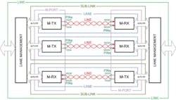
A typical M-PHY link, as shown in Figure 4, comprises two SUB-LINKs, one in each direction, coupled with a management function. Each lane consists of a TX, RX, and a line that connects the TX and the RX using differential wire. Specifications are defined at the pins of the M-TX and M-RX. Each SUB-LINK can have multiple lanes in the same direction. For some applications, there is provision for a low-cost optical converter.
Figure 4. Typical M-PHY Link
Source: MIPI Alliance
Adding to its flexibility, M-PHY offers a choice of interfaces known as Type-I and Type-II. The difference is determined by the signaling scheme. Type-I uses pulse width modulation (PWM) while Type-II uses system-clock synchronous non-return-to-zero (NRZ) signaling. Type-I can function with independent local clock references on each side of the link while Type-II requires a shared reference clock between the two ends of the line. The Type-I and Type-II interfaces are not interoperable.
To cover different speed ranges, M-PHY supports the use of multiple gears or speeds. The default gear for Type-I is PWM-G1, ranging from 3 to 9 Mb/s. There are six gears with incremental 2x higher speed ranges (PWM-G2 to G7) and one gear below the default speed range (PWM-G0).
The default HS gear (HS-G1) operates at two different speeds, 1.25 Gb/s or 1.45 Gb/s, along with two other optional speeds at incremental 2x the default speed. The use of a gear-based architecture along with the different clocking options allows designers to target data rates and power dissipation based on system requirements.
With its higher data rates and greater versatility and sophistication, M-PHY testing requires the use of dedicated tools to verify performance and interoperability and efficiently debug problems. This includes the capability to acquire M-PHY traffic with 8b/10b decode, form packets, and disassemble for analysis on an oscilloscope. For M-PHY interface testing, a 6-GHz oscilloscope can be used for HS-G1 while an 8-GHz instrument is needed for the other HS gears to capture 70-ps rise-time accuracies within ±5% of the specification.
Signal Accessibility
Mobile designs are tiny in nature with high packing density. Probing these signals using any regular probe is a challenging task. The signal traces cannot be extended easily to meet a specific choice of probe. To probe signals from a miniature circuit, probes with a wide range of accessories like miniature tips, micro clips, and solder tips, are needed.
The probes should support both the HS and LP modes with variance of different voltage levels, multiple speeds of operations, and different terminations. The mobile devices also must be tested at extreme environmental conditions. In such cases, probes should provide sufficiently long lead accessories such as XL cables and probe tips that can sustain operation in a temperature chamber.
Summary
The emergence of MIPI technologies solves a number of problems for the mobile industry, ranging from the need to expand feature sets and improve battery life to increasing bandwidth and lowering costs through component reuse. The MIPI specification is designed for versatility and flexibility. A number of analysis, verification, and debug tools along with specialized probes have already appeared on the market to go with a rapidly expanding MIPI ecosystem.
About the Author
Pavan Alle is a product manager at Tektronix and has more than 10 years experience in the electronics design and testing industry. Mr. Alle received a BSEE degree in electronics and communication engineering from Osmania University and completed management education at the Indian Institute of Management, Ahmedabad. Tektronix, Performance Oscilloscopes, 14150 S.W. Karl Braun Dr., Beaverton, OR 97077, 800-833-9200, e-mail: [email protected]


