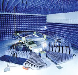
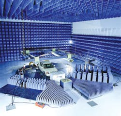
Full-Vehicle Automotive EMC Testing in a Semi-Anechoic Chamber
Courtesy of ETS-Lindgren
Reducing interference from extraneous sources obviously is important when a radio receiver is being developed. Ideally, you would eliminate all signals other than the test signal you deliberately generated. This is the function of a screened room or shielded enclosure. Similarly, if you needed to measure emissions from a piece of equipment, doing so inside a screened room would minimize the errors caused by signals from other sources.
How well you can constrain electric, magnetic, or electromagnetic fields depends on many variables including field strength, distance to the source, frequency, and characteristics of the material used to construct the enclosure. Static electric fields have the highest impedance and are completely controlled by a Faraday cage, which approximates a closed conductive shell. According to Gauss’s Law, no charge can exist inside a conductor. It all resides on the outer surface.
Charge is redistributed on the outer surface of the enclosure to force the internal field to zero—the principle behind screened room performance. The principle works as well in reverse, confining even very strong electric fields inside a test chamber so that the field outside is zero.
Faraday cages have almost ideal performance for electrostatic fields, work very well for electromagnetic fields but with some qualifications, and have little effect on low-frequency magnetic fields. For low-frequency electric fields, such as found in a power plant, a Faraday cage can be made from hardware cloth, commonly called chicken wire, and still be nearly as effective as if it were made from solid sheet metal.
For higher frequencies, the size of the holes between the conductors and the resistance of the conductors themselves become important, and the enclosure is more correctly considered a shield than a Gaussian surface. Even a small gap is significant at high frequencies, so seams and access doors can be problem areas.
The distance to the source influences shielding applications because high-frequency electric and magnetic fields can exist separately over a short distance—the near field. At larger distances, the far field region, the fields are related to each other as an electromagnetic field that has the characteristic 377-? impedance of free space.
For EMC testing, anechoic chambers attempt to match the 377-? field impedance with RF absorbing material. If an exact match is achieved, all the field energy is absorbed and none reflected. Typically, absorbers provide a large degree of absorption, resulting in only a small portion of the energy being reflected.
It is not practical to perform EMC immunity tests at an open-air test site (OATS). On the other hand, when subjecting an EUT to a strong field, it is important that the field really is uniform so that performance measurements are meaningful. Many test specifications call for less than 6-dB field strength variation within the test volume. Because anechoic chambers provide a matched impedance termination, the internal field distribution depends largely upon the antenna characteristics and is predictable.
Mode-stirred chambers, sometimes called reverberation chambers, also are shielded enclosures but actively use reflected energy rather than suppress it. The largest reflection coefficient results from the greatest impedance mismatch, so some of these chambers are internally silver-plated to achieve the highest possible conductivity. Plating really does make a large difference because, at frequencies above a few hundred megahertz, the skin depth is very small.
A simple reverberation chamber has fixed geometry, usually rectangular or tapered. This means that the positions of maximum and minimum field strength are predictable at a given frequency. In turn, this implies large variations in test results depending on the relationship between the max/min points and the position of the EUT.
If the dimensions are large compared to the wavelengths being used, operation is referred to as being overmoded. This means that there are hundreds of 3-D standing wave patterns that result from slight changes in frequency. Large rotating paddles inside a mode-stirred chamber sufficiently alter the internal reflections. Therefore, rather than having a fixed pattern, the field can be described by a statistical distribution.
Particularly for high field-strength testing, this approach requires lower power amplifiers than would be needed with an anechoic chamber for the same maximum field strength. Nevertheless, because the field is statistically uniform rather than truly constant, test routines must take this into account.
Low-frequency magnetic shielding involves much lower impedances than does electric or electromagnetic field shielding. The magnetic properties of the enclosure material become more important at low frequencies. High permeability material shunts magnetic lines of force around the shielded object. However, permeability varies with field strength, falling to a low value if the field is sufficiently strong to cause saturation.
Very often, multiple shields are nested one within the other, each layer reducing the field strength by a number of decibels. The outer layer must be able to handle the full field without saturating. Steel might be used in this role even though its permeability is much lower than MµMetal, Conetic, or similar special shielding alloys. If only two layers were used, the inner one might be MµMetal, assuming the steel layer had reduced the field strength sufficiently to avoid MµMetal saturation.
Low-permeability, highly conductive metal reduces high-frequency magnetic fields by creating eddy currents that, in turn, develop opposing magnetic fields. So, in addition to layers of MµMetal and steel, a highly conductive layer may be used.
Anechoic Chambers
Assuming an anechoic chamber does not have leaks from seams or door openings, the absorbers within the chamber largely determine performance. Below 100 MHz, ferrite tiles are a much more compact solution than lossy pyramidal foam absorbers, which typically need to be many feet long at these frequencies. As frequency increases, however, pyramidal absorbers become more practical and are commonly used up to and, more recently, above 1 GHz. Some manufacturers combine a foam pyramid with a ferrite tile base to extend the frequency range.
Kefeng Liu, director for RF materials at ETS-Lindgren, discussed some of the factors considered when the company recently launched Model EMC-20PCL Foam Absorbers. “To maintain both low- and high-frequency range absorber performance, the wave impedance balance between the ferrite and foam absorbers is very critical to the success of a hybrid absorber design,” he said. “More absorptive loading will allow the hybrid absorber to work better at high frequencies; however, too much absorptive loading in the foam will bounce the energy off the foam, preventing the ferrite material from participating in the absorption at low frequencies. Conversely, too little absorptive loading will weaken the absorptive performance in the high-frequency range.”
For the wideband absorbers, Mr. Liu referred to the proprietary conductive carbon as well as the mix of fire-resistant salts used to impregnate the low-density polyurethane foam. Manufacturing features a two-step process that ensures even distribution of the carbon but isolates it from the fire-retardant chemicals. Apparently, isolation promotes the stability of the absorber substrate’s electrical properties. In addition to handling up to 200-V/m field strength and offering good attenuation characteristics from 80 MHz through 40 GHz, the absorbers are relatively small at 20 inches high and have blunt tips that reduce damage in use.
Ferrite tile absorbers also are precision components but, unlike polyurethane foam absorbers, are immune to fire, humidity, and chemicals. Tiles have different thicknesses depending on the range of frequencies to be attenuated. Waves leaving the tile after reflection from the back surface are out of phase with those entering the front surface, creating a resonant condition. This is equivalent to a deep null in the return-loss response.
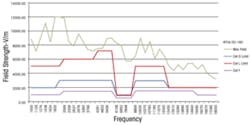
Figure 1. High RF Testing Levels Developed in a Mode-Tuned Chamber
Courtesy of DNB Engineering
Reverberation Chambers
Many manufacturers and researchers have commented on the advantages of mode-stirred reverberation chambers for testing at high field-strength levels. RTCA DO-160 Cat G, for example, calls for at least 6,000 V/m field strength from about 2 GHz to 6 GHz (Figure 1), which becomes much more practical to achieve with a high-Q resonant chamber. And, compared to an OATS or semi-anechoic chamber (SAC), reverberation chambers often are a better match to the actual confined and reflecting space in which an EUT is operated.
These chambers have been built in a wide range of sizes, but the mutually prime 8 m x 5 m x 3 m dimensions of QinetiQ’s medium-size chamber at Farnborough, U.K., provide the starting point for a simple analysis. A rectangular chamber with sides of length g, h, i will have resonant frequencies fnmp, where n, m, and p are integers. In any combination of n, m, and p, only one can be zero:
where: c = speed of light ? 3E8 m/s
A large number of modes are desirable to support chamber isotropy. As discussed briefly in an announcement of a recently commissioned large reverberation chamber at Elite Electronic Engineering, isotropy describes the equal interaction of the field with the EUT from all directions. Also, from a reciprocal point of view, a reverberation chamber may provide a more comprehensive emissions testing environment because the direction of an emission is unimportant.1
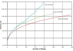
Figure 2. Behavior of Reverberation Chamber Modes at Low Frequency
In an isotropic environment, the EUT does not have to be repositioned along each of the three axes as is the case with SAC or fully anechoic room (FAR) testing. It also means that the antenna does not have to be repositioned at a number of different heights to achieve testing in both polarizations.
Homogeneity is another important chamber characteristic, and this is largely dependent on the number of modes and how well they are stirred. The function of the tuner is to change the boundary conditions sufficiently that the superposition of max and min field strengths becomes uniformly distributed throughout the test volume, averaged over a complete tuner revolution.
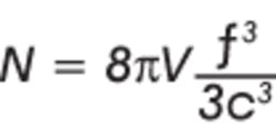
Figure 2 is a plot of the number of modes vs. frequency. For the blue curve, n, m, and p were constrained to be ?5, for the green curve ?20. The red curve represents Weyl’s formula, an asymptotic limit that the number of modes N approaches at high frequency as n, m, and p become very large:2
where: V = the chamber volume in m3
High values for n, the index associated with the largest chamber dimension, still correspond to relatively low frequencies when m and p are small. The lowest resonance, 35 MHz in this case, is set by the dimensions of the two longest sides of the chamber. For the QinetiQ chamber, the lowest practical test frequency is around 105 MHz, approximately three times the lowest resonant frequency, corresponding theoretically to about 45 modes.
Nevertheless, as Figure 2 shows, at relatively low frequencies, the number of modes does not change smoothly with frequency, nor does the density of low-frequency modes increase no matter how large n, m, and p become. A recent paper postulates that deviation from Weyl’s curve is inherent at low frequencies because insufficient degrees of freedom are involved, resulting in a distribution that is not Gaussian. Tests performed in a real chamber measured a kurtosis of 3.7 rather than 3.0 as is associated with a normal distribution. A chamber’s performance at a sufficiently high frequency does not exhibit this problem.3
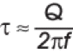
Mode-stirred chambers efficiently support high field-strength levels with moderate power input because they are high-Q resonators. Q can be between 1,000 and 10,000 as measured in the reverberation chamber at York University, and the field decay time constant associated with it also can be large, leading to complications in pulse testing.
At sufficiently high frequency
So, if Q = 10,000, f = 1 GHz, ? ? 1.6 µs. For the field to decay to a small value, as much as 10 µs should elapse between pulses. Limiting the pulse repetition rate may not be practical for some tests, and the paper that presented details of the York University chamber also described adding absorber material to reduce a chamber’s Q. Clearly, there is a trade-off between power efficiency and field decay time.
In fact, chamber characterization testing is done with the chamber empty and again with an amount of absorber material to simulate loading by the EUT. Q values cited by several sources tend to be lower than theoretical by a factor of about five at high frequencies and as much as a factor of 50 at low frequencies. These discrepancies typically are attributed to surface finish, seams, and similar imperfections in the chamber construction.4
Other Types of Enclosures
If you are a high-ranking diplomat or military officer that needs to prepare secret reports at various locations around the world, you need effective but portable EMC security. As José Bouza, Vector Technologies’ vice president for engineering and operations, explained, “We produce portable, soft-sided shielding tents to protect classified information from being hacked into while government officials are traveling in hostile countries. In addition to the original application, we also offer the tents as precompliance test chambers. They provide a low noise floor and can be configured as a simple shielded enclosure or complete with fiber-optic instrument control capabilities. In addition to the enclosure’s 82-dB shielding effectiveness, it has the advantage of easy setup and removal.”
Chambers in Action
It is possible to contain very high test fields or exclude a wide range of low-level background noise. The best solution depends entirely on how well shielded the test environment must be to address your application. Mr. Bouza’s portable RF-secure tents would seem to be well suited to precompliance emissions testing. Perhaps the convenience the tent offers will lead to more thorough precompliance testing and fewer full compliance failures.
Is the traditional need for OATS testing being supplanted by tests in a SAC? ETS-Lindgren’s Mr. Liu is seeing the transition taking place, aided by the proliferation of new electronic devices requiring test and the continuing changes in test specifications.
And, as cars add more electronic systems, the susceptibility of those systems to RF interference has taken on a serious safety aspect. To investigate the Toyota accelerator pedal saga, NASA engineers used a large reverberation chamber installed at a Chrysler facility in Michigan. According to a company spokesperson, the ETS-Lindgren chamber was chosen because it is a whole-vehicle-size reverberation chamber that includes a dynamometer to support testing under realistic operating conditions.
You may not need a dynamometer, but a clear idea of the tests to be performed will help you decide among the available ranges of shielded rooms, SACs, FARs, and stirred-mode chambers. Be sure to discuss the details with a few select vendors to minimize surprises when you are finally standing inside ready to start testing.
1. “Elite’s New Mode Tuned Chamber,” http://www.elitetest.com/latest-news/elites-new-mode-tuned-chamber1.html, 2009.2.
2. Albrecht, M., et al, “Source Stirring Technology for Automotive Antenna Measurement,” International Microwave Symposium Digest, 2008, pp. 238-241.
3. Cozza, A., and Monsef, F., “How a Physical Definition of Overmodedness Can Explain Local Statistically Non-Compliancy,” Proceedings EMC Europe 2011 Symposium, 2011.
4. Dawson, J. F., and Arnaut, L., “Reverberation (Mode Stirred) Chambers for Electromagnetic Compatibility,” http://www.compliance-club.com/archive/old_archive/030530.htm
